Moon Control Products Ltd. Tel.: +44 (0)1202 599922 www.mooncontrolproducts.com Page | 38
CAN communicaon protocol describes a way of transming informaon between devices. The denion of CAN layer is
the same as the open systems interconnecon model OSI, each layer communicates with the same layer in another device,
the actual communicaon takes place adjacent layers in each device, but the devices only interconnect by the physical
media of the physical layer in the model. CAN standard denes data link layer and physical layer in the mode. The physical
layer of CAN bus is not strictly required, it can use a variety of physical media such as twisted pair Fibre. The most
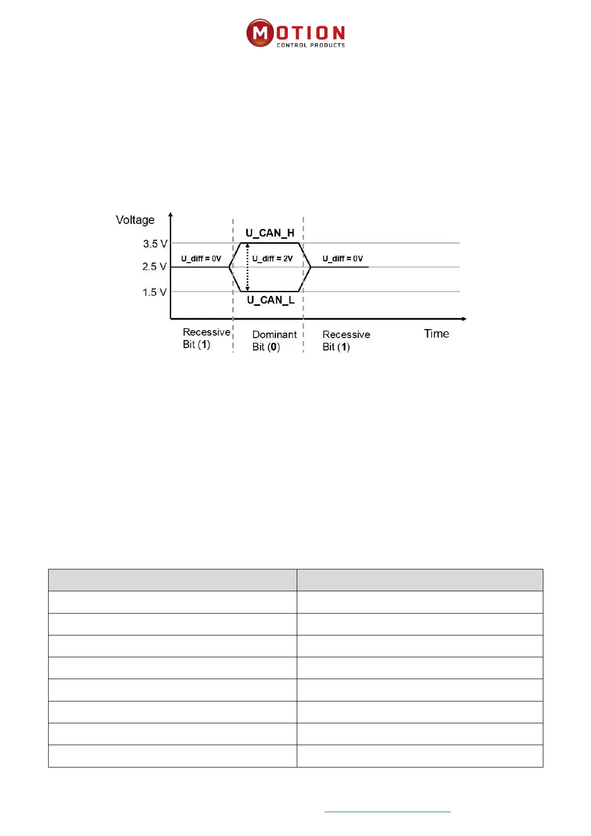
commonly used is twisted pair signal, sent by dierenal voltage transmission (commonly used bus transceiver). The two
signal lines are called CAN_H and CAN_L. The stac voltage is approximately 2.5V, then the state is expressed as a logical 1,
also called hidden bit. It represents a logic 0 when CAN_H is higher than the CAN_L, we called it apparent bit, then the
voltage is that CAN_H = 3.5V and CAN_L= 1.5V, apparent bit is in high priority. The names and funcons of the CAN
communicaon interface pins are shown in Table 7-4.
Table 7-3 CAN Signal idencaon
Note:
1. The CAN_L and CAN_H feet of all slaves can be directly connected, and the wiring is carried out in series.
2. Please use shielded twisted pair as far as possible for communicaon cables.
3. The longest distance that can theorecally communicate with various baud rates is shown in Table 10-7.
4. The servo wheel does not need to be connected to an external 24V power supply to supply power to CAN.
Table 7-4 The max. distance at dierent baud rate are shown in following table (Theory)