Home
Motorola
Radio
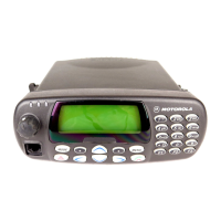
MTM800 FuG
Motorola MTM800 FuG Installation Manual
4
of 1
of 1 rating
268 pages
Give review
Manual
Specs
To Next Page
To Next Page
Loading...
MTM800 FuG/
MTM800 FuG ET
Installation Manual
Installationshandbuch
*68015000553*
68015000553-KC
Januar
2017
©
2017 Motorola Solutions, Inc. All rights reserved
2
Table of Contents
English
3
Copyrights
3
Contents
5
List of Figures
9
List of Tables
13
Icon Conventions
17
Scope of This Manual
19
1.1 Safety Information
19
1.2 MTM800 FuG/MTM800 FuG ET Manuals and User Guides
19
Model Information and Accessories
21
2.1 Model Descriptions
21
2.2 Sales Model Nomenclature
21
2.3 Mobile Terminal Model Information
22
2.4 Model Specifications
23
2.5 MTM800FuG Accessories-to-Model Chart
25
2.6 MTM800FuG ET Accessories-to-Model Chart
29
Vehicle Preparation
35
3.1 General Guidelines for Radio Installation
35
3.2 Uninstalling the Radio
36
3.3 Installing DC Power Cable
36
3.3.1 DC Power Cables
39
3.4 Installing Ignition Sense Cable
39
3.4.1 Ignition Sense Cables
40
Radio Installation
41
4.1 Dashboard Installation
41
4.1.1 Installing the Radio in an Automotive Dashboard
41
4.1.2 Mounting the Radio in the Frame
41
4.1.3 Removing the Radio from the Frame
42
4.2 Desktop Installation
43
4.2.1 Desktop Installation Planning
43
4.2.2 Desktop Installation
43
4.3 MTM800FuG Remote Mount Installation
45
4.3.1 Installing the Remote Mount Enhanced Control Head onto the Remote Mount Trunnion
46
4.3.2 Installing the Remote Mount Enhanced Control Head in a DIN Mount Bracket
47
4.3.3 Inserting the Remote Mount Enhanced Control Head with the DIN Mount Bracket into the DIN Frame
48
4.3.4 Adding Extra Accessories to the Remote Head by Expansion Cable
49
4.3.5 Installing the Accessories Expansion Cable
50
4.4 MTM800 FuG ET Remote Mount Installation
50
4.4.1 Ethernet Cables
55
4.4.2 Installing the Remote Mount Ethernet Control Head (eCH) onto the Remote Mount Trunnion
56
4.4.3 Installing the Remote Mount Ethernet Control Head (eCh) in a DIN Mount Bracket
57
4.4.4 Inserting the Remote Mount Ethernet Control Head (eCH) with the DIN Mount Bracket into the DIN Frame
58
4.4.5 Adding Extra Accessories to the Ethernet Control Head (eCH) and Telephone Style Control Head (TSCH)
59
4.4.6 Telephone Style Control Head (TSCH)
63
4.4.6.1 Mounting TSCH Cradle onto Slim Bracket
66
4.5 Motorcycle Mount Enhanced Control Head Installation
69
4.5.1 Installing Motorcycle Mount Enhanced Control Head
70
4.5.2 MTM800FuG Mechanical Parts
73
4.5.3 Installing Motorcycle Mount TELCO Cable (PMKN4030_)
73
4.5.4 Adding Extra Connectivity to the Motorcycle Mount Enhanced Control Head
74
4.6 Data Expansion Head Enhanced Installation
74
4.6.1 Data Expansion Head Enhanced Radio without Control Head
74
4.6.2 Data Box Radio
74
4.6.3 Data Expansion Head Enhanced with Third Party Control Head
75
4.6.4 Junction Box Installation
76
4.6.5 Installing Junction Box
78
4.6.6 Connecting Accessories to the Junction Box
78
4.6.7 Connectors on the Junction Box
79
4.6.8 Connection Plan for the Junction Box Accessory Terminal
80
4.6.9 Installing the Cable
82
4.6.10 Connection Plan for Accessory Connector Kit
83
4.6.11 Radios with Data Expansion Head Enhanced
84
4.6.12 Standard Radios without Data Expansion Head Enhanced
84
4.6.13 Standard Radios without Ethernet Data Expansion Head
85
4.7 Installing Trunnion
85
Connectors and PIN Assignment
89
5.1 Transceiver Rear Side
89
5.2 Accessory Connection Plan
91
5.3 Re-crimp Procedure
93
5.4 Connectors and Pin Assignment of Data Expansion Head Enhanced and Remote Head Enhanced
93
5.4.1 10-Pin TELCO Connector
94
5.4.2 25-Pin subD Connector
95
5.4.3 9-Pin subD Connector
96
5.5 Connectors and Pin Assignment of Ethernet Expansion Head
97
5.5.1 Ethernet Control Head Interfaces
97
5.5.2 SIM Interface
98
5.5.3 9-Pin subD Connector
98
5.6 SIM Card Reader
99
5.7 Connector and Pin Assignment of the Enhanced Control Head
100
5.8 Connector and Pin Assignment of Ethernet Control Head (eCH)
104
5.9 Connecting Cables
107
5.9.1 Motorcycle Mount TELCO Cable
107
5.9.2 Remote Mount Cables
107
5.9.3 Accessories Expansion Cable
107
5.9.4 Connector and Pin Assignment for Cradle (Telephone Style Control Head)
109
5.9.5 Ethernet Cables
110
5.9.6 Remote Ethernet Control Head Y-Cable (Accessories Expansion Cable)
111
5.9.7 Telephone Style Control Head Y-Cable (Accessories Expansion Cable)
111
5.9.8 Radio-to-Junction Box
112
5.9.9 Data Expansion Head Enhanced Radio-to-Data Device
114
5.9.10 Data Expansion Head Enhanced Radio-to-Fist Microphone
114
5.9.10.1 Removing the Existing Coiled Cord Cable
115
5.9.11 Radio-to-Data Device: Active Data Cable
116
External Equipment Installation
117
6.1 Vehicle Antenna Installation
117
6.1.1 Mobile Radio Operation and EME Exposure
117
6.1.2 Selecting an Antenna Site
117
6.1.3 Installing Antenna
118
6.1.4 Completing Radio Installation
119
6.2 Installing External Speaker
119
Appendix A: Service Information – EIA
121
Appendix B: Service Information – AME
123
Appendix C: Service Information – Americas
127
Appendix D: Warranty and Service Support
129
Appendix E: Product Specific Information for Digital Terminals Type MT953CG
131
Deutsch
133
Copyright
133
Inhalt
135
Verzeichnis der Abbildungen
139
Verzeichnis der Tabellen
143
Verwendete Symbole
147
Umfang dieses Handbuchs
149
1.1 Sicherheitshinweise
149
1.2 MTM800 Fug/MTM800 Fug ET Hand- und Benutzerhandbücher
149
Modellinformationen und Zubehör
151
2.1 Modellbeschreibungen
151
2.2 Bezeichnung von Modellen
151
2.3 Informationen zu den Mobilmodulen
152
2.4 Modellspezifikationen
153
2.5 MTM800FuG, Zuordnungsdiagramm Zubehör-zu-Modell
155
2.6 MTM800FuG ET, Zuordnungsdiagramm Zubehör-zu-Modell
160
Vorbereiten des Fahrzeugs
165
3.1 Allgemeine Richtlinien für die Installation von Funkgeräten
165
3.2 Deinstallation des Funkgeräts
166
3.3 Installation des DC Stromversorgungskabels
166
3.3.1 Gleichstromkabel
169
3.4 Zündungserkennungskabel installieren
169
3.4.1 Zündungserkennungskabel
170
Installation des Funkgeräts
171
4.1 Einbau in das Armaturenbrett
171
4.1.1 Einbau des Funkgerätes in das Armaturenbrett
171
4.1.2 Montage des Funkgeräts am Rahmen
171
4.1.3 Funkgerät aus dem Rahmen nehmen
172
4.2 Festinstallation
173
4.2.1 Planung einer Festinstallation
173
4.2.2 Festinstallation
174
4.3 MTM800FuG, Remote-Installation
175
4.3.1 Erweitertes Bedienteil zur Remote-Montage auf der Halterung für die Remote-Montage anbringen
177
4.3.2 Erweitertes Bedienteil zur Remote-Montage auf einer DIN-Halterung anbringen
178
4.3.3 Erweitertes Bedienteil zur Remote-Montage mit der DIN-Halterung in den DIN-Rahmen einführen
178
4.3.4 Weiteres Zubehör mittels Zubehörkabel an das Bedienteil anschließen
179
4.3.5 Zubehör-Verlängerungskabel anschließen
180
4.4 MTM800 FuG ET Remote-Montage
181
4.4.1 Ethernet-Kabel
185
4.4.2 Ethernet-Bedienteil zur Remote-Montage (eCh) auf der Halterung für Remote-Montage anbringen
187
4.4.3 Ethernet-Bedienteil zur Remote-Montage (eCH) in eine DIN-Halterung montieren
188
4.4.4 Ethernet-Bedienteil zur Remote-Montage (eCh) in einen DIN-Einbaurahmen montieren
188
4.4.5 Zusätzliches Zubehör an Ethernet-Bedienteil zur Remote-Montage (eCh) und Bedienteil in Telefonausführung (TSCH) anbringen
189
4.4.6 Bedienteil in Telefonausführung (TSCH)
193
4.4.6.1 TSCH-Auflage auf Montageblech montieren
196
4.5 Installation des erweiterten Bedienteils zur Motorradmontage
199
4.5.1 Erweitertes Bedienteil zur Motorradmontage installieren
200
4.5.2 MTM800FuG, mechanische Teile
203
4.5.3 TELCO-Kabel der Motorradhalterung montieren (PMKN4030_)
204
4.5.4 Zusätzliche Anschlussmöglichkeiten am erweiterten Bedienteil für die Motorradmontage
204
4.6 Installation des erweiterten Datendienstmoduls
204
4.6.1 Erweitertes Modul für Datendienste ohne Bedienteil
204
4.6.2 Datenfeld-Funkmodul
204
4.6.3 Erweitertes Modul für Datendienste mit einem Bedienteil von einem Drittanbieter
205
4.6.4 Installation der Anschlussbox
206
4.6.5 Anschlussdose installieren
208
4.6.6 Zubehör an Anschlussdose anschließen
208
4.6.7 Anschlüsse an der Anschlussbox
209
4.6.8 Anschlussplan für Klemmenblock der Anschlussbox
210
4.6.9 Kabel installieren
212
4.6.10 Anschlussplan für Zubehöranschlusssatz
213
4.6.11 Funkgeräte mit erweitertem Modul für Datendienste
214
4.6.12 Standard-Funkgeräte ohne erweitertes Modul für Datendienste
214
4.6.13 Standard-Funkgeräte ohne Ethernet-Erweiterungsmodul für Datendienste
215
4.7 Befestigungshalterung installieren
215
Anschlüsse und PIN-Belegung
221
5.1 Rückseite des Transceivers
221
5.2 Zubehör-Anschlussplan
223
5.3 Verfahren zum erneuten Zusammenklemmen
225
5.4 Anschlüsse und Pinbelegung des erweiterten Moduls für Datendienste und des erweiterten Remote-Moduls
226
5.4.1 10-poliger TELCO-Anschluss
227
5.4.2 25-poliger D-Sub-Anschluss
228
5.4.3 9-poliger D-Sub-Anschluss
229
5.5 Anschlüsse und Pin-Belegung des Ethernet-Erweiterungsmoduls
230
5.5.1 Schnittstellen des Ethernet-Bedienkopfes
230
5.5.2 SIM-Schnittstelle
231
5.5.3 9-poliger D-Sub-Anschluss
231
5.6 SIM-Kartenleser
232
5.7 Anschluss- und Pin-Belegung des erweiterten Bedienteils
233
5.8 Anschluss- und Pin-Belegung des Ethernet-Bedienteils (eCH)
237
5.9 Anschluss der Kabel
240
5.9.1 Motorradhalterung, TELCO-Kabel
240
5.9.2 Kabel für Remote-Montage
240
5.9.3 Zubehör-Verlängerungskabel
240
5.9.4 Anschluss und Pin-Belegung bei Auflage (Bedienteil in Telefonausführung)
242
5.9.5 Ethernet-Kabel
243
5.9.6 Y-Kabel für das abgesetzte Ethernet-Bedienteil (Zubehör-Erweiterungskabel)
244
5.9.7 Y-Kabel für das Bedienteil in Telefonhörerausführung (Zubehör-Erweiterungskabel)
244
5.9.8 Funkgerät zu Anschlussbox
245
5.9.9 Erweitertes Modul für Datendienste des Funkgeräts zu Datengerät
247
5.9.10 Funkgerät mit erweitertem Modul für Datendienste zu Handmikrofon
247
5.9.10.1 Vorhandenes gewendeltes Kabel entfernen
248
5.9.11 Funkgerät zu Datengerät: Aktives Datenkabel
249
Installation von externen Geräten
251
6.1 Installation der Antenne am Fahrzeug
251
6.1.1 Betrieb des mobilen Funkgeräts und Belastung durch elektromagnetische Strahlung
251
6.1.2 Antennenstandort wählen
251
6.1.3 Antenne installieren
252
6.1.4 Installation des Funkgeräts durchführen
253
6.2 Externen Lautsprecher installieren
254
Anhang A: Service-Informationen - EIA
255
Anhang B: Service-Informationen – AME
257
Anhang C: Service-Informationen – Nord-, Mittel- und Südamerika
261
Anhang D: Garantie und Service-Support
265
Anhang E: Produktspezifische Informationen für digitale Mobilfunkgeräte vom Typ MT953CG
267
Other manuals for Motorola MTM800 FuG
Feature User Guide
158 pages
Quick Start Guide
2 pages
4
Based on 1 rating
Ask a question
Give review
Questions and Answers:
Need help?
Do you have a question about the Motorola MTM800 FuG and is the answer not in the manual?
Ask a question
Motorola MTM800 FuG Specifications
General
Frequency Bands
380-430 MHz
IP Rating
IP54
Channels
Up to 1000
Encryption
TEA1, TEA2, TEA3
Operating Temperature
-30°C to +60°C
Channel Spacing
12.5 kHz
Related product manuals
Motorola TETRA MTM800
254 pages
Motorola MTM700
328 pages
Motorola MTM5400
133 pages
Motorola TETRA MTM5200
152 pages
Motorola TETRA MTM5400
152 pages
Motorola TETRA MTM5500
152 pages
Motorola Dimetra MTM300
58 pages
Motorola MTM5 00 Series
120 pages
Motorola TETRA MTM5000 Series
152 pages
Motorola MTP3150
144 pages
Motorola MTP6550
15 pages
Motorola MOTOTRBO DM4600
12 pages