4.6.7
Connectors on the Junction Box
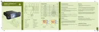
Figure 42: Connectors on the Junction Box – Front Panel
Connectors on the Junction Box - Front Panel
1= Connecting cable from
Junction Box to MTM5200/
MTM5400/MTM800 FuG
(rear side 26-pin accessory
connector) for installation
purpose only.
PMKN4101_ (length 6 m)
PMKN4102_ (length 4 m)
PMKN4103_ (length 2 m)
2 = Connector for accessory terminal
pin 1 SPEAKER +
pin 2 SPEAKER -
pin 3 EXT_PTT
pin 4 IGNITION SENSE
pin 5 EXT_ALARM
pin 6 EMERGENCY
pin 7
3 = Visor Micro-
phone connector
PMMN4087_
CAUTION: PIN 4: To short the ignition to ground, use an adapter between the radio and the
accessory connector. Interference can cause radio to hang.
68015000553-KC
Chapter 4: Radio Installation
Send Feedback 79

 Loading...