Chapter 5
Connectors and PIN Assignment
5.1
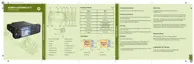
Transceiver Rear Side
Figure 53: Location of Accessory Connector – Rear Side
CAUTION: The accessory connections shown are not compatible to some other models of
Motorola Solutions radios. Check the appropriate accessory or technical manual for further
information.
Table 49: 26–PIN Accessory Connector
PIN Function Description
1 UART1_TXD / USBx_D+ USB 1.1 – Default Host
RS232 or UART2 – Alternative Setting
NOTICE: When Expansion Head is connected –
the connection is USB1.1. UART2 is configured
on DB9 interface on the expansion Head. The ra-
dio monitors DB9 interface to detect cable con-
nection/disconnection based on PIN voltage level
of RX and DTR lines. When Expansion Head is
not connected – the connection can be config-
ured to UART2 in the CPS codeplug (default set-
ting is USB1.1).
NOTICE: If it is not a radio with BSI SW, then us-
ing codeplug setting it can be changed to UART2,
else it is USB1.1.
2 UART1_RXD / USBx_D-
3 UART1_RTS / USBx_VBUS
4 GND_USBx
5 1-WIRE 1-Wire standard port (pulled via 2K2 to 5 V inside U600),
Data for RMN5054_ Microphone
6 KEYFAIL / FLASH Key load (pulled via 10 K to 5 V)
Flash input (>10 V triggers Flash mode)
7 SWB + A+ voltage (limited to 14 V) with 1 A current limitation
8 GND_MAIN Main and power ground
9 SPEAKER- Loudspeaker (PA) out-
put –
WARNING:
Table continued…
68015000553-KC
Connectors and PIN Assignment
Send Feedback 89

 Loading...