5.7
Connector and Pin Assignment of the Enhanced Control Head
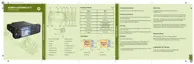
Figure 61: Mobile Microphone Port Connector of the Enhanced Control Head
Number Description
1 View of the Mobile Microphone Port Connector of the Enhanced Control Head
NOTICE: The keypad labeling of the control head may vary according to the specific customer/
country concerns.
Table 56: Mobile Microphone Port Connector of the Enhanced Control Head
Mobile Micro-
phone Port Pin
Default Functions Alternative
Functions
USB Functions RS232 Func-
tions
NOTICE: The connector enters one of the 5 modes automatically based on the automatic
detection of the connected accessory.
1 1-WIRE 1-WIRE 1-WIRE 1-WIRE 1-WIRE
2 GPIO_3 PTT GP Input or
Output
GP Input or Out-
put
RS-232-RTS
3 SPEAKER SPEAKER SPEAKER SPEAKER SPEAKER
4 GPIO_2 GPIO_2 INPUT GP Input or
Output
DATA - RS-232-RXD
5 GND GND GND GND GND
6 OPT 5V HIGH Impedance OPT 5V VBUS OPT 5V
7 MIC + MIC + MIC + MIC + MIC +
8 GPIO_1 GPIO_1 INPUT GP Input or
Output
DATA + RS-232-TXD
9 GPIO_4 HOOK GP Input or
Output
GP Input or Out-
put
RS-232-CTS
10 GPIO_0 GPIO_0 INPUT GP Input or
Output, PWR
ON
GP Input or Out-
put, PWR ON
GP Input or
Output, PWR
ON
68015000553-KC
Chapter 5: Connectors and PIN Assignment
100 Send Feedback

 Loading...