5.3
Re-crimp Procedure
To use accessories from MTM800 such as RLN4858_ and GKN6272_ with the rear connector of the
radio, follow the re-crimp procedure using the crimp pins provided with PMLN5072_ connector kit.
These accessories do not require to be re-crimped when used with the Data Junction Box
GMLN5089_.
Process:
1 Cut and remove nickel plated pins from wire.
2 Strip the insulation from the end of the wires (2 mm to 4 mm).
3 Place the new gold plated crimp pin (from the PMLN5072_ kit) on the gauge slot on the crimp
tool.
4 Insert wire into the wire slot of the crimp pin.
5 Apply pressure to the crimp tool handle, until wire is crimped by the pin.
5.4
Connectors and Pin Assignment of Data Expansion Head
Enhanced and Remote Head Enhanced
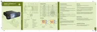
Figure 57: Data Expansion Head Enhanced – Front View and Connector Location
J302
12
345678
910
1
1425
5
69
113
1 2 3
Number Description
1 10-Pin TELCO Connector, Front View,
CAUTION:
Connector to the Control Head.
2 25-Pin subD Connector
3 9–Pin subD Connector
68015000553-KC
Chapter 5: Connectors and PIN Assignment
Send Feedback 93

 Loading...