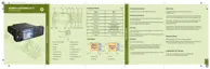
Figure 40: Example of Configuration with Remote Control Terminal and External SIM Card
Reader
Number Description
1 TELCO Connector (10-Pin)
2 Front DATA connector
3 9-Pin subD Connector (female), 8-Wire RS232 PEI Interface or External SIM Card
(depends on CPS configuration)
4 Data Expansion Head Enhanced
5 Terminal Transceiver Box
6 Accessory Connector (26-Pin)
7 SMA GPS Connector
8 Power Connector
9 BNC Antenna Connector
10 BNC RF Connector
11 8–wired RS232 Cable
12 Remote Control Terminal via RS232
13 External SIM Reader Cable
14 External SIM Card Reader
4.6.4
Junction Box Installation
The data junction box (GMLN5089_) assists the easy installation for dash and remote mount
configurations.
The junction box enables the customer adding a laptop to the remote configuration, connecting a visor
microphone, various accessories, or fist microphone.
68015000553-KC
Chapter 4: Radio Installation
76 Send Feedback

 Loading...