PIN Function Description
22
tomatically switched de-
pending on which accessory
is detected.
UART2_RXD / USBy_RX RS232 or UART2 RXD /
2nd USB2.0 (OTG) D-
23 EMERGENCY Emergency Input (Pulled
via 24K9 to A+) – Pull
low to power on
24 UART_CTS RS232 or UART1 /
UART2 CTS input
25 IGNITION Ignition input (through
series 15K) – Pull > 10
V to power on
26 EXTERNAL ALARM External Alarm output
(Pulled via 4K7 to A+)
CAUTION: PIN 25: If the ignition line is not used, it must be grounded for example connected to
pin 8. Interference can cause radio to hang.
NOTICE: PINs 13 and 15 cannot be used (nor configured) at the same time.
5.2
Accessory Connection Plan
CAUTION: The accessory connections shown are not compatible to some other models of
Motorola radios. Check the appropriate accessory or technical manual for further information.
Ensure correct position of the accessory connector.
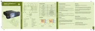
Figure 54: Accessory Connector
68015000553-KC
Chapter 5: Connectors and PIN Assignment
Send Feedback 91

 Loading...