Figure 34: Motorcycle Mount Enhanced Control Head - Front Side.......................................................69
Figure 35: Motorcycle Installation...........................................................................................................70
Figure 36: Upward Movement................................................................................................................ 72
Figure 37: Downward Movement............................................................................................................72
Figure 38: Motorcycle Mount Enhanced Control Head Mounted in a Trunnion......................................73
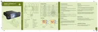
Figure 39: Data Box Radio Interface Description................................................................................... 74
Figure 40: Example of Configuration with Remote Control Terminal and External SIM Card Reader... 76
Figure 41: Remote Mount Installation with Junction Box........................................................................77
Figure 42: Connectors on the Junction Box – Front Panel.....................................................................79
Figure 43: Connectors on the Junction Box – Rear Panel..................................................................... 80
Figure 44: Connection Plan for the Speaker.......................................................................................... 80
Figure 45: Connection Plan for the Alarm Relay.................................................................................... 81
Figure 46: Connection Plan for the Emergency Switch.......................................................................... 81
Figure 47: Connection Plan for the Ignition Sense Cable.......................................................................82
Figure 48: Connection Plan for External PTT.........................................................................................82
Figure 49: Terminal into High Profile Trunnion (GLN7317_).................................................................. 85
Figure 50: Terminal into Key Locked Mount Trunnion (RLN4779_)....................................................... 86
Figure 51: Top of Dash Mount................................................................................................................87
Figure 52: Below Dash Mounting........................................................................................................... 88
Figure 53: Location of Accessory Connector – Rear Side......................................................................89
Figure 54: Accessory Connector............................................................................................................ 91
Figure 55: 26–Pin Accessory Connector................................................................................................ 92
Figure 56: Connecting Diagrams............................................................................................................92
Figure 57: Data Expansion Head Enhanced – Front View and Connector Location..............................93
Figure 58: Remote Head Enhanced – Front View and Connector Location...........................................94
Figure 59: Ethernet Expansion Head Enhanced – Front View and Connector Location........................97
Figure 60: Ethernet Expansion Head with SIM Card Reader................................................................. 99
Figure 61: Mobile Microphone Port Connector of the Enhanced Control Head................................... 100
Figure 62: Enhanced Motorcycle Control Head –Rear View................................................................ 101
Figure 63: Remote Enhanced Control Head – Rear View....................................................................101
Figure 64: Enhanced Motorcycle Control Head – Rear Connectors.................................................... 101
Figure 65: View of the Ethernet Control Head (eCH) with Mobile Microphone Port Connector........... 104
Figure 66: Ethernet Control Head – Rear Connectors......................................................................... 105
Figure 67: Motorcycle Mount TELCO Cable.........................................................................................107
Figure 68: Remote Mount Cable.......................................................................................................... 107
Figure 69: Accessories Expansion Cable.............................................................................................108
Figure 70: Mobile to Control Head Ethernet Cable Pin Diagram..........................................................110
Figure 71: Mobile to Mobile Ethernet Cable Pin Diagram.................................................................... 110
Figure 72: RECH Y-Cable Pin Diagram............................................................................................... 111
68015000553-KC
List of Figures
10 Send Feedback

 Loading...