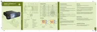
NOTICE: Connectors on the Motorcycle Enhanced Control Head, and Remote Enhanced
Control Head are the same. The housings and the cables are different.
Number Description
1 10-Pin Telco Connector
2 25-Pin Back Connector
Table 57: 10-Pin Telco Connector
Pin Function Description
1 AUDIO + Balanced Audio + (Bidirectional)
2 NC Not Connected
3 BUS + This is used for communication between the radio and an Enhanced
Control Head.
4 AUDIO - Balanced Audio - (Bidirectional)
5 NC Not Connected
6 GND Ground
7 Radio On/Off
Control
This is the Enhanced Control Head service request input. A level of 5 V
indicates that the Enhanced Control Head needs to communicate with
the radio. In addition, it switches on the voltage regulators of the radio.
The idle state is a level below 0.6 V.
8 SCI_TX This if for communication between the radio and the Enhanced Control
Head.
9 FLT_A + This voltage is at battery voltage level and is available as long as the
radio is connected to the supply voltage. The maximum current is 300
mA. A fuse in the radio prevents further circuit damage in case of short-
ing this pin to ground.
10 Analog Ground Analog Ground
Table 58: 25-Pin Back Connector
Pin Function Description Default
1 GPIO_9 NGCH GPIO4 Output: Active for dura-
tion of call (car radio
mute). Can be used as
a trigger to a local log-
ger device.
2 GPIO_6 External PTT for MIC_REAR_2 PTT Input, TX audio
from MIC_REAR_2
3 GPIO_8 NGCH GPIO2 (CPS configurable) Disabled
4 GPIO_3 GCAI PIN 2 Mobile Microphone Port, Exter-
nal PTT or MIC_REAR_1, Ground Pin 8 to
activate MIC_REAR_1
PTT Input, TX audio
from MIC_REAR_1
5 VBUS_1B GCAI PIN 6: 5 V Supply Disabled
Table continued…
68015000553-KC
Chapter 5: Connectors and PIN Assignment
102 Send Feedback

 Loading...