• Remote Mount installation with Ethernet Telephone Style Control Head (TSCH)
• Dual Control Head with two eCH
• Dual Control Head with two TSCH
• Dual Control Head with a combination of eCH and TSCH
• Multi-Radio Control installation with eCH
• Multi-Radio Control Installation with TSCH
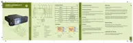
Table 45: MTM800 FuG ET Configurations – Graphics Description
Number Description
1 MTM800 FuG ET Transceiver
2 Ethernet Expansion Head – PMLN7009_
3 Telephone Style Control Head (TSCH), Roman – PMWN4025_
4 Ethernet Control Head (eCH) Roman – PMWN4024_
5 Ferrite Clamps – 91012044001
6 Mobile Ethernet Cable, 5 m – PMKN4140_
7 Mobile Ethernet Cable, 3 m – PMKN4141_
8 Mobile to Mobile Ethernet Cable, 3 m – PMKN4177_
IMPORTANT:
All Ethernet cables shown in the following illustrations require three ferrite clamps, Part Number
91012044001, with two turns of wire around them. Manually install the first ferrite clamp
approximately 60 cm away from the Control Head and with a minimum spacing of 3 cm
between the next two ferrite clamps.
For single Control Head installation, connect the Control Head to port one of the Ethernet
Expansion Head.
For Mobile to Mobile Ethernet Cables, connect the end of the cable marked EEH1 to Ethernet
port one of one transceiver and connect EEH2 to Ethernet port two of another transceiver.
Figure 12: Remote Mount Installation with Ethernet Control Head (eCH) PMWN4024_
68015000553-KC
Chapter 4: Radio Installation
Send Feedback 51

 Loading...