EasyManuals Logo

Motorola ST7000 Basic Service Manual

Motorola ST7000
92 pages
To Next Page IconTo Next Page
To Previous Page IconTo Previous Page
Page #83 background imageLoading...
Page #83 background image
5.7.3.4
Installing the Internal Antenna Module Assembly
Procedure:
Insert the internal antenna module assembly and press it down firmly until it snaps in place.
Figure 38: Installing the Internal Antenna Module Assembly
5.7.3.5
Installing the Main Board
Procedure:
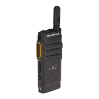
1 Assemble the top flex board-to-board connector to the main PCB.
Figure 39: Installing the Top Flex Board-to-Board Connector
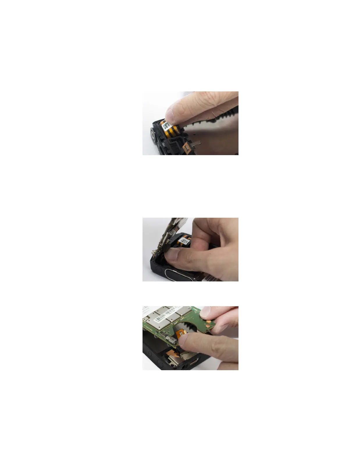
2 Lift the USB board-to-board flex connector and slot in the main PCB.
Figure 40: Inserting the Main PCB
3 Attach the USB flex board-to-board connector to the main board.
MN002952A01-AH
Chapter 5: Maintenance
83

Table of Contents

Other manuals for Motorola ST7000

Questions and Answers:

Question and Answer IconNeed help?

Do you have a question about the Motorola ST7000 and is the answer not in the manual?

Motorola ST7000 Specifications

General IconGeneral
Weight170g
Dimensions132 x 49.5 x 23.4 mm
Ingress ProtectionIP54
Operating Temperature-30°C to +60°C
RF Power Output1W
Battery LifeUp to 14 hours (standard battery)
TETRA Air InterfaceETSI EN 300 392
SecurityAir Interface Encryption (AIE)
Power Output1W
Frequency Bands380-400 MHz, 410-430 MHz, 450-470 MHz, 806-870 MHz
Frequency Range380-400 MHz, 410-430 MHz, 450-470 MHz, 806-870 MHz

Related product manuals