Medium Frame 2 & 3 Stage Snow Throwers
72
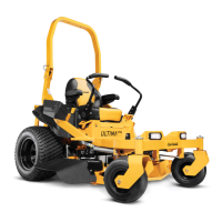
6. Remove the screws holding the Bearing Housing on
each side. See Figure 7.14.
NOTE: This is a good opportunity to inspect the
Auger Bearing for signs of wear.
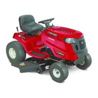
7. Pull the auger from the housing. Slight rotation of
the assembly may be necessary to pull the Impeller
Shaft clear of the rear bearing. See Figure 7.15.
NOTE: The most common cause of Auger Gear-
Box damage is an impact with solid objects.
This damage is not warrantable. Use of
proper Shear Pins helps prevent gearbox
damage, but does not guarantee protection.
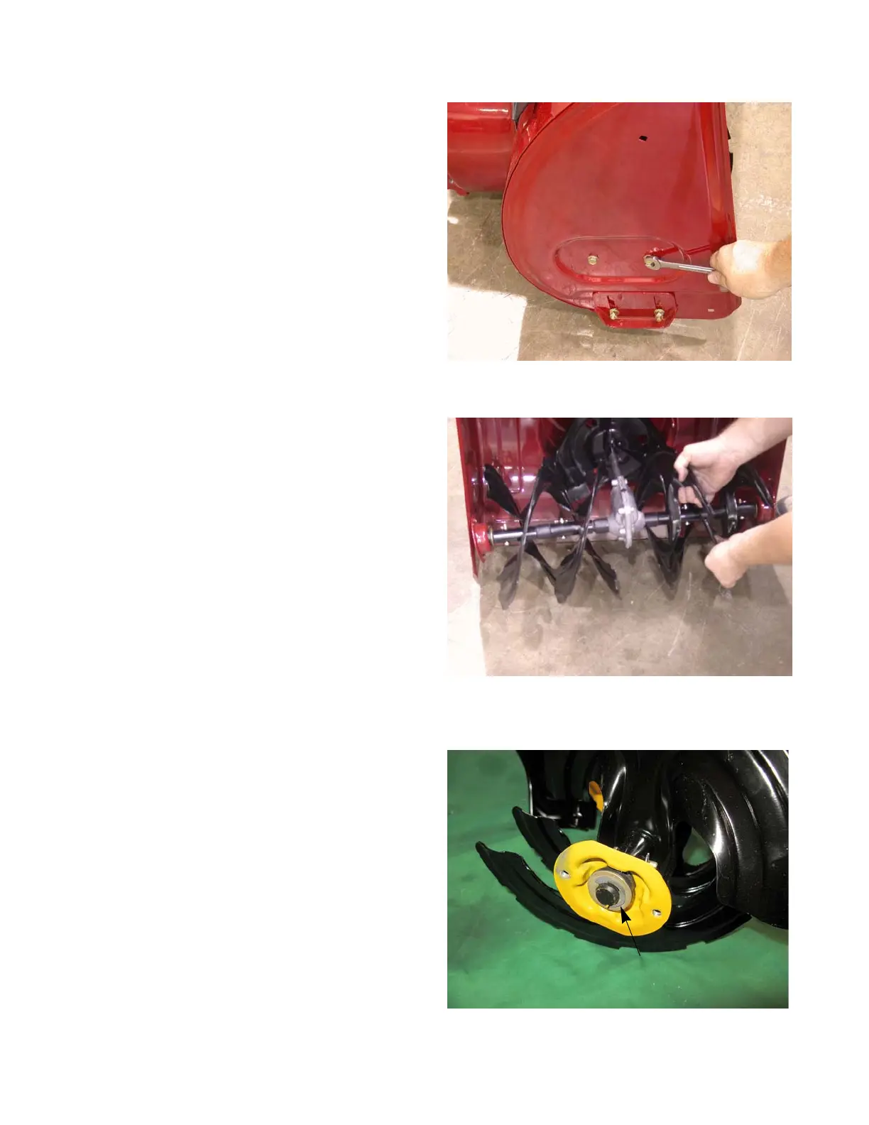
8. Remove the Bearing Cup, Hex Flange Bushing and
washer from each end of the output shaft.
NOTE: Some models may have an E-ring that holds
the bushing to the end of the shaft. See Fig-
ure 7.16.
 Loading...