Auger Housing and Gear Box
73
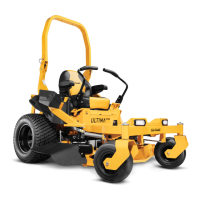
NOTE: 3-stage units have augers on the front and back of
the Gear Box called Accelerators. See Figure 7.17.
9. Pry off the front cap.
10. Remove the screw and washer from the end of the
Input Shaft.
11. Remove the Shear Pin.
12. Slide the Accelerator, washer and spacer off of the
front of the Gear Box.
13. Slide the impeller off of the D section of the Gear Box
Input Shaft.
NOTE: If the unit is a 3-stage gear box, remove the rear
Accelerator.
14. Remove the shear pins.
15. Slide the augers and spacers off of the Gear Box
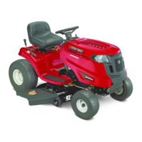
Assembly.
NOTE: Note the orientation and location of all of the spac-
ers as they are removed.
16. Inspect the spacers and bushings. Check for possible
damage to augers. See Figure 7.18.
17. Examine the removed Auger Assembly: If it failed;
because of something other than normal wear, iden-
tify and correct the cause before returning the snow
thrower to service.
18. Install the Auger Assembly by following the previous
steps in reverse order.
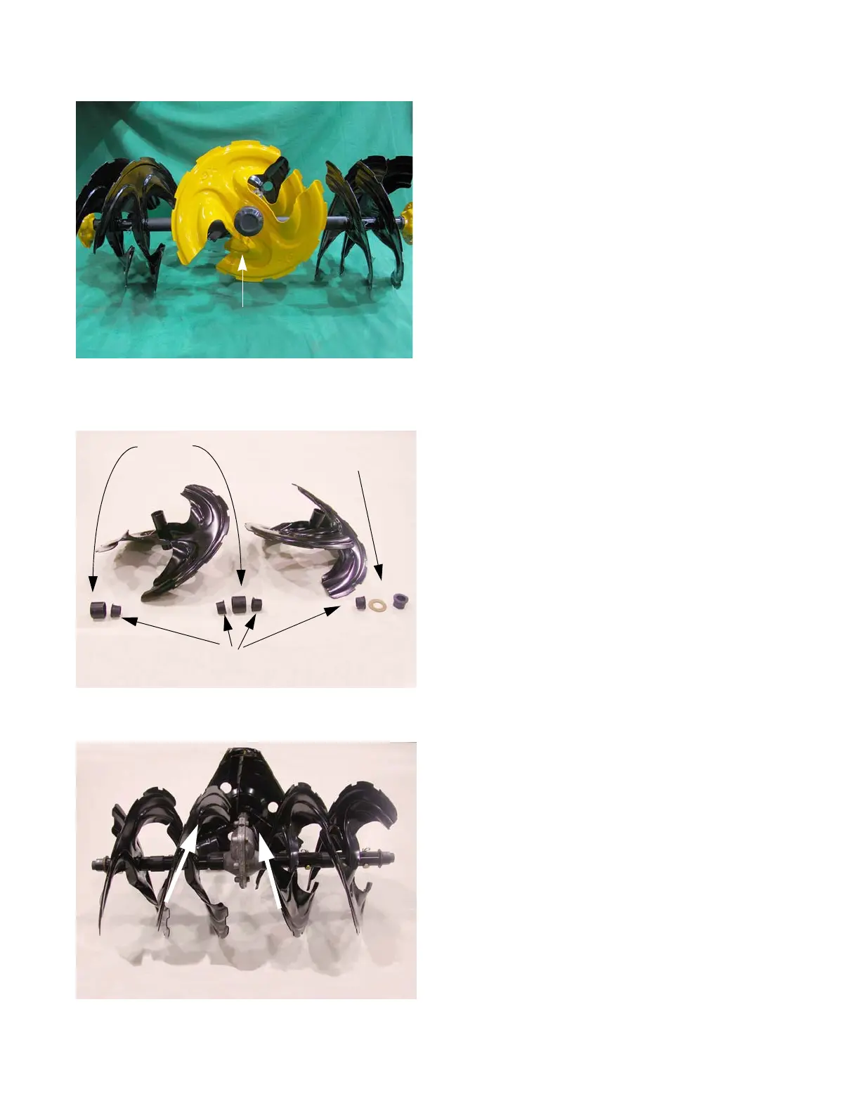
NOTE: When the augers are installed correctly, the fore-
most blades will have an inward slant. See Figure
7.19.
19. Test run the snow thrower in a safe area before
returning to service.
Figure 7.18
Flange bushings
Spacers
Hex Bushing
 Loading...