21
Temposonics
®
R-Series SSI
Operation Manual
Temposonics
®
R-Series SSI
Operation Manual
4.4 Styles and installation of Temposonics
®
RD4
Sensor electronics housing
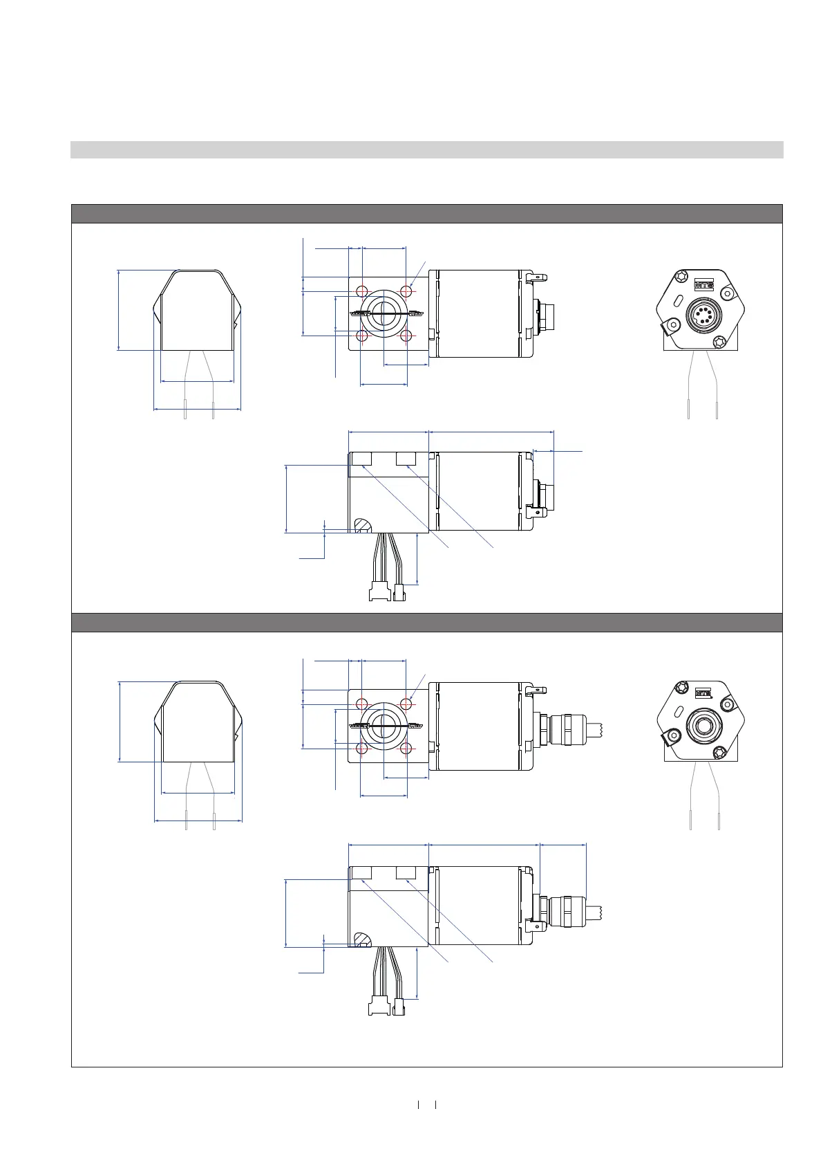
Fig. 13: Temposonics
®
RD4 sensor electronics housing with bottom cable entry
Sensor electronics housing with bottom cable entry, example: Connector outlet D70
24.7
(0.97)
Mounting block
45 (1.77)
50
(2)
Ø 18
(Ø 0.7)
45
(1.78)
70
(2.76)
12
(0.46)
24.7
(0.97)
Ø 6.2
(Ø
0.24)
41
(1.61)
49
(1.93)
8.2
(0.32)
7.7
(0.3)
45
(1.77)
23
(0.91)
45
(1.77)
49
(1.93)
41
(1.61)
2
(0.08)
Ø 26.5
(Ø 1.04)
38
(1.5)
Mounting block
45
(1.77)
Sensor electronics housing
70
(2.76)
12
(0.46)
Sensor electronics housing
Sensor electronics
housing
24.7
(0.97)
(0.97)
(0.3)
8.2
(0.32)
Sensor electronics
housing
Recommendation:
Use M6×45 (ISO 4762) screws for sensor fastening.
Fastening torque: 6 Nm
Recommendation:
Use M6×45 (ISO 4762) screws for sensor fastening.
Fastening torque: 6 Nm
25
(0.98)
50
(1.97)
Ø 19
( Ø 0.75)
24.7
(0.97)
Mounting block
45 (1.77)
50
(2)
Ø 18
(Ø 0.7)
45
(1.78)
24.7
(0.97)
Ø 6.2
(Ø
0.24)
41
(1.61)
49
(1.93)
8.2
(0.32)
7.7
(0.3)
45
(1.77)
23
(0.91)
38
(1.5)
Sensor electronics
housing
Recommendation:
Use M6×45 (ISO 4762) screws for sensor fastening.
Fastening torque: 6 Nm
45
(1.77)
49
(1.93)
41
(1.61)
Ø 26.5
(Ø 1.04)
24.7
(0.97)
24.7
(0.97)
7.7
(0.3)
8.2
(0.32)
Sensor electronics
housing
25
(0.98)
Ø 19
( Ø 0.75)
38
(1.5)
Mounting block
45
(1.77)
Sensor electronics housing
62
(2.44)
Recommendation:
Use M6×45 (ISO 4762) screws for sensor fastening.
Fastening torque: 6 Nm
50
(1.97)
26
(1.02)
Sensor electronics housing
62
(2.44)
26
(1.02)
Ø 6.2
(Ø 0.24)
Sensor electronics housing with bottom cable entry, example: Cable outlet FXX / HXX / PXX / RXX
24.7
(0.97)
Mounting block
45 (1.77)
50
(2)
Ø 18
(Ø 0.7)
45
(1.78)
70
(2.76)
12
(0.46)
24.7
(0.97)
Ø 6.2
(Ø
0.24)
41
(1.61)
49
(1.93)
8.2
(0.32)
7.7
(0.3)
45
(1.77)
23
(0.91)
45
(1.77)
49
(1.93)
41
(1.61)
2
(0.08)
2
(0.08)
Ø 26.5
(Ø 1.04)
38
(1.5)
38
(1.5)
Mounting block
45
(1.77)
Sensor electronics housing
70
(2.76)
12
(0.46)
Sensor electronics housing
Sensor electronics
housing
24.7
(0.97)
24.7
(0.97)
7.7
(0.3)
8.2
(0.32)
Sensor electronics
housing
Recommendation:
Use M6×45 (ISO 4762) screws for sensor fastening.
Fastening torque: 6 Nm
Recommendation:
Use M6×45 (ISO 4762) screws for sensor fastening.
Fastening torque: 6 Nm
25
(0.98)
50
(1.97)
Ø 19
( Ø 0.75)
24.7
(0.97)
Mounting block
45 (1.77)
50
(2)
Ø 18
(Ø 0.7)
45
(1.78)
24.7
(0.97)
Ø 6.2
(Ø
0.24)
41
(1.61)
49
(1.93)
8.2
(0.32)
7.7
(0.3)
45
(1.77)
23
(0.91)
38
(1.5)
Sensor electronics
housing
Recommendation:
Use M6×45 (ISO 4762) screws for sensor fastening.
Fastening torque: 6 Nm
45
(1.77)
49
(1.93)
41
(1.61)
Ø 26.5
(Ø 1.04)
24.7
(0.97)
24.7
(0.97)
7.7
(0.3)
8.2
(0.32)
Sensor electronics
housing
25
(0.98)
Ø 19
( Ø 0.75)
38
(1.5)
Mounting block
45
(1.77)
Sensor electronics housing
62
(2.44)
Recommendation:
Use M6×45 (ISO 4762) screws for sensor fastening.
Fastening torque: 6 Nm
50
(1.97)
26
(1.02)
Sensor electronics housing
62
(2.44)
26
(1.02)
Ø 6.2
(Ø
0.24)
Ø 6.2
(Ø 0.24)
Controlling design dimensions are in millimeters and measurements in ( ) are in inches

 Loading...