31
Temposonics
®
R-Series SSI
Operation Manual
Temposonics
®
R-Series SSI
Operation Manual
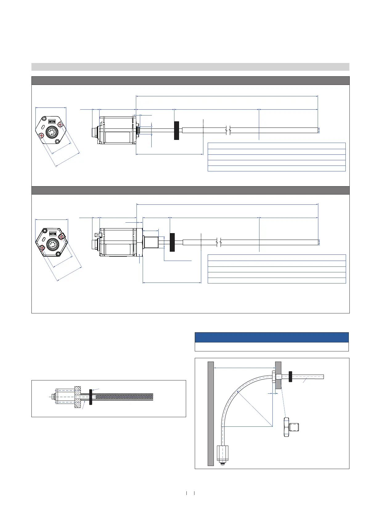
Fig. 31: Temposonics
®
RF base unit with ring magnet (top) RF with threaded flange with ring magnet (bottom)
Fig. 32: Sensor with support tube
Fig. 33: Clearances for installation
4.6 Styles and installation of Temposonics
®
RF
Controlling design dimensions are in millimeters and measurements in ( ) are in inches
NOTICE
Smaller radiuses cause damage to the flexible sensor rod.
Non-magnetic support tube, inside Ø 9.4 (0.37)
500 (20) recommended
≥ 300 (≥ 11.81)
Position magnet
10
(0.4)
A/F 46
Flange M18×1.5-6g
¾"-16 UNF-3A
Customized support tube
required e.g. Ø 12.7 × 1.65
(Ø 0.5 × 0.65),
inside Ø 9.4 (Ø 0.37),
non-magnetic
R > 250
(R > 9.84)
RF-C
12
(0.46)
Sensor electronics housing
58
(2.28)
Null zone
61
(2.40)
Stroke length
150…20,000
(6…787)
Dead zone
see table
49
(1.93)
43.7
(1.72)
34.6
(1.36)
Not flexible
107
(4.21)
Ø 8 ± 0.23
(Ø 0.31 ± 0.009)
Ø 8 ± 0.23
(Ø 0.31 ± 0.009)
Flange »M«:
M18×1.5-6g
Flange »S«:
¾"-16 UNF-3A
53
(2.09)
46
(1.81)
Sensor electronics housing
58
(2.28)
12
(0.46)
10
(0.39)
25
(0.98)
Null zone
51
(2.01)
Not flexible
97
(3.82)
Stroke length
150…20,000
(6…787)
Dead zone
see table
34.6
(1.36)
Magnet
Total length
Note: Tolerance of total length has no influence on the stroke length.
Stroke length
Up to 7620 mm (300.00 in.)
Up to 10,000 mm (393.70 in.)
Up to 15,000 mm (590.55 in.)
Up to 20,000 mm (787.00 in.)
Tolerance of total length
+8 mm (0.31 in.) / −5 mm (0.20 in.)
+15 mm (0.59 in.) / −15 mm (0.59 in.)
+15 mm (0.59 in.) / −30 mm (1.18 in.)
+15 mm (0.59 in.) / −45 mm (1.77 in.)
Dead zone
94 mm (3.70 in.)
100 mm (3.94 in.)
120 mm (4.72 in.)
140 mm (5.51 in.)
Note: Tolerance of total length has no influence on the stroke length
Stroke length
Up to 7620 mm (300.00 in.)
Up to 10,000 mm (393.70 in.)
Up to 15,000 mm (590.55 in.)
Up to 20,000 mm (787.00 in.)
Tolerance of total length
+8 mm (0.31 in.) / −5 mm (0.20 in.)
+15 mm (0.59 in.) / −15 mm (0.59 in.)
+15 mm (0.59 in.) / −30 mm (1.18 in.)
+15 mm (0.59 in.) / −45 mm (1.77 in.)
Dead zone
94 mm (3.70 in.)
100 mm (3.94 in.)
120 mm (4.72 in.)
140 mm (5.51 in.)
.
7
(0.28)
11.5
(0.45)
RF-M / -S
Note the following information when mounting a RF sensor:
1. Always insert the flexible sensor rod in a support tube (e.g.
pressure rod HD / HL / HP or HFP profile). The support tube with
an inside diameter of 9.4 mm (0.37 in.) consists of non-magnetic
material. The support tube can be straight or bent (note the
bending radius in Fig. 33).
2. Do never bend beyond the minimum bending radius of 250 mm
(9.84 in.)
3. Note the minimum distance to a spatial limitation of 300 mm
(11.81 in.), when mounting / dismounting the sensor (Fig. 33).
4. Note that the first 107 mm (4.21 in.) (for RF-C) respectively
97 mm (3.82 in.) (for RF-M) of the sensor rod are not flexible.
Controlling design dimensions are in millimeters and measurements in ( ) are in inches
12
(0.46)
Sensor electronics housing
58
(2.28)
Null zone
61
(2.40)
Stroke length
150…20,000
(6…787)
Dead zone
see table
49
(1.93)
43.7
(1.72)
34.6
(1.36)
Not flexible
107
(4.21)
Ø 8 ± 0.23
(Ø 0.31 ± 0.009)
Ø 8 ± 0.23
(Ø 0.31 ± 0.009)
Flange »M«:
M18×1.5-6g
Flange »S«:
¾"-16 UNF-3A
53
(2.09)
46
(1.81)
Sensor electronics housing
58
(2.28)
12
(0.46)
10
(0.39)
25
(0.98)
Null zone
51
(2.01)
Not flexible
97
(3.82)
Stroke length
150…20,000
(6…787)
Dead zone
see table
34.6
(1.36)
Magnet
Total length
Note: Tolerance of total length has no influence on the stroke length.
Stroke length
Up to 7620 mm (300.00 in.)
Up to 10,000 mm (393.70 in.)
Up to 15,000 mm (590.55 in.)
Up to 20,000 mm (787.00 in.)
Tolerance of total length
+8 mm (0.31 in.) / −5 mm (0.20 in.)
+15 mm (0.59 in.) / −15 mm (0.59 in.)
+15 mm (0.59 in.) / −30 mm (1.18 in.)
+15 mm (0.59 in.) / −45 mm (1.77 in.)
Dead zone
94 mm (3.70 in.)
100 mm (3.94 in.)
120 mm (4.72 in.)
140 mm (5.51 in.)
Note: Tolerance of total length has no influence on the stroke length
Stroke length
Up to 7620 mm (300.00 in.)
Up to 10,000 mm (393.70 in.)
Up to 15,000 mm (590.55 in.)
Up to 20,000 mm (787.00 in.)
Tolerance of total length
+8 mm (0.31 in.) / −5 mm (0.20 in.)
+15 mm (0.59 in.) / −15 mm (0.59 in.)
+15 mm (0.59 in.) / −30 mm (1.18 in.)
+15 mm (0.59 in.) / −45 mm (1.77 in.)
Dead zone
94 mm (3.70 in.)
100 mm (3.94 in.)
120 mm (4.72 in.)
140 mm (5.51 in.)
.
A/F 46

 Loading...