27
Temposonics
®
R-Series SSI
Operation Manual
Temposonics
®
R-Series SSI
Operation Manual
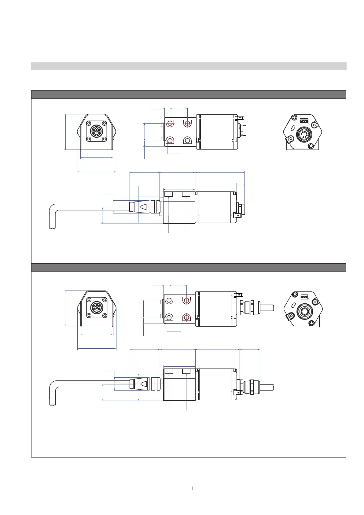
4.5 Styles and installation of Temposonics
®
RT4
Fig. 24: Temposonics
®
RT4 sensor electronics housing
Sensor electronics housing
Sensor electronics housing, example: Connector outlet D70
7.7
(0.3)
24.7
(0.97)
24.7
(0.97)
Sensor electronics housing
70
(2.8)
50
(1.97)
45
(1.78)
14
(0.5)
57
(2.2)
25
(0.98)
Null zone
51
(2.01)
Stroke length
25…2540
(1…100)
Dead zone
64
(2.5)
Flange »T«: ¾"-16 UNF-3A
71
(2.8)
Ø 10
(Ø 0.39)
38
(1.5)
44.5
(1.75)
51
(2.01)
44.5
(1.75)
51
(2.01)
Sensor
electronics
housing
45
(1.8)
49
(1.9)
41
(1.6 )
Side view
(second sensor electronics not shown)
Recommendation:
Use M6×45 (ISO 4762) screws for sensor fastening.
Fastening torque: 6 Nm
14
(0.5)
57
(2.2)
25
(0.98)
71
(2.8)
Null zone
51
(2.01)
2.5
(0.10)
Stroke length
25…2540
(1…100)
Dead zone
64
(2.5)
Ø 10
(Ø 0.39)
Magnet
Flange »D«: ¾"-16 UNF-3A
Flange »M«: M18×1.5-6g
50
(1.97)
Mounting block
45 (1.8)
Mounting block
45 (1.8)
45
(1.78)
Sensor electronics housing
62
(2.44)
Side view
(second sensor electronics not shown)
Recommendation:
Use M6×45 (ISO 4762) screws for sensor fastening.
Fastening torque: 6 Nm
7.7
(0.3)
24.7
(0.97)
24.7
(0.97)
Sensor
electronics
housing
26
(1.02)
Ø 6.2
(Ø 0.24)
8.2
(0.32)
12
(0.46)
23
(0.91)
Ø 18
(Ø 0.7)
38
(1.5)
23
(0.91)
Ø 18
(Ø 0.7)
A/F 44.5
A/F 44.5
Sensor electronics housing, example: Cable outlet FXX / PXX / RXX
7.7
(0.3)
24.7
(0.97)
24.7
(0.97)
Sensor electronics housing
70
(2.8)
50
(1.97)
45
(1.78)
14
(0.5)
57
(2.2)
25
(0.98)
Null zone
51
(2.01)
Stroke length
25…2540
(1…100)
Dead zone
64
(2.5)
Flange »T«: ¾"-16 UNF-3A
71
(2.8)
Ø 10
(Ø 0.39)
38
(1.5)
44.5
(1.75)
51
(2.01)
44.5
(1.75)
51
(2.01)
Sensor
electronics
housing
45
(1.8)
49
(1.9)
41
(1.6 )
45
(1.8)
49
(1.9)
41
(1.6 )
Side view
(second sensor electronics not shown)
Magnet
Recommendation:
Use M6×45 (ISO 4762) screws for sensor fastening.
Fastening torque: 6 Nm
14
(0.5)
57
(2.2)
25
(0.98)
71
(2.8)
Null zone
51
(2.01)
2.5
(0.10)
Stroke length
25…2540
(1…100)
Dead zone
64
(2.5)
Ø 10
(Ø 0.39)
Magnet
Flange »D«: ¾"-16 UNF-3A
Flange »M«: M18×1.5-6g
50
(1.97)
Mounting block
45 (1.8)
45
(1.78)
Sensor electronics housing
62
(2.44)
Side view
(second sensor electronics not shown)
Recommendation:
Use M6×45 (ISO 4762) screws for sensor fastening.
Fastening torque: 6 Nm
7.7
(0.3)
24.7
(0.97)
24.7
(0.97)
Sensor
electronics
housing
26
(1.02)
Ø 6.2
(Ø 0.24)
8.2
(0.32)
12
(0.46)
23
(0.91)
Ø 18
(Ø 0.7)
38
(1.5)
23
(0.91)
Ø 18
(Ø 0.7)
Controlling design dimensions are in millimeters and measurements in ( ) are in inches

 Loading...