25
Temposonics
®
R-Series SSI
Operation Manual
Temposonics
®
R-Series SSI
Operation Manual
Notice for metric threaded flanges
Fig. 18: Notice for metric threaded flange M18×1.5-6g based on DIN ISO 6149-1
Thread
(d
1
×P)
d
2
d
3
d
4
d
5
+0.1
0
L
1
+0.4
0
L
2
L
3
L
4
Z°
±1°
RD4-C
M18×1.5-6g 55 ≥ 13 24.5 19.8 2.4 28.5 2 26 15°
RD4-G / -M
M18×1.5-6g 30 ≥ 13 24.5 19.8 2.4 28.5 2 26 15°
Ød
5
Ra 3.2
Ra 3.2
Pitch diameter
A
A
Thread
(d
1
× P)
Ød
3
(Reference)
A
Ød
2
Ød
4
(Gauging)
This dimension applies when
tap drill cannot pass through
≤ R0.4
R0.3
R0.1
Z°
4
5
°
±
5
°
3
L
1
L
2
L
4
Controlling design dimensions are in millimeters
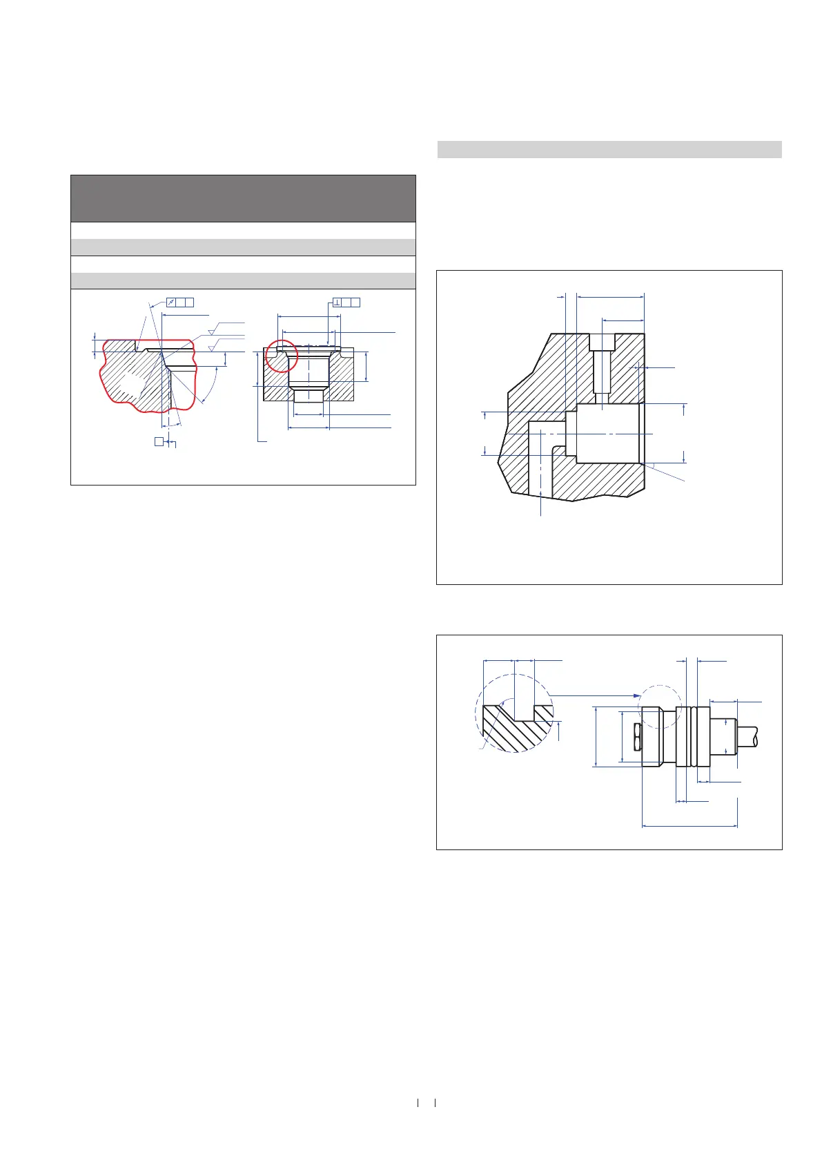
4.4.2 Installation of RD4 with pressure fit flange
Cylinder mounting
Install the rod using the pressure fit flange. Seal it off by means of
the O-ring and the back-up ring. Block the pressure fit flange using a
shoulder screw (Fig. 19). For details of the pressure fit flange »S« see
Fig. 20. Also note the mounting examples in Fig. 21 and Fig. 22.
Controlling design dimensions are in millimeters and measurements in ( ) are in inches
Note for cylinder installation:
• The position magnet should not grind on the sensor rod.
• The piston rod drilling (≥ Ø 13 mm (≥ Ø 0.51 in.)) depends on the
pressure and piston speed.
• Adhere to the information relating to operating pressure.
• Protect the sensor rod against wear.
Fig. 19: Example of mounting detail: Shoulder screw 8-M6 (ISO 7379) with internal hexagon
Fig. 20: Pressure fit flange »S« details
14.7
(0.58)
44.7
4.8
(0.2)
7.1
(0.28)
26.9 +0.03
(1.06 +0.001)
22.9
(0.9)
12.7
(0.5)
(0.17)
(0.4)
(0.23)
Ø 22.9
(Ø 0.9)
45°
(1.26)
5
(0.2)
20.3
(0.8)
20
Bore
27 H7
(1.07)
15°
2.5
(0.1)
For side cable entry: Ø 10…20 (Ø 0.39…0.79)
bore for cable to electronics housing
For bottom cably entry: Ø 13…17 (Ø 0.51… 0.67)
bore to push single wires through

 Loading...