42
Temposonics
®
R-Series SSI
Operation Manual
Temposonics
®
R-Series SSI
Operation Manual
5. Operation
5.1 Getting started
The sensor is factory-set to its order sizes and adjusted, i.e. the start
of the measuring range is specified in resolution steps.
Example: SSI value 51000 corresponds to a start of measuring range
of 51 mm with a resolution of 1 µm
If necessary, the SSI sensors can be re-adjusted using
the service tool described below.
Diagnostic display
LEDs (red / green) in the sensor electronics housing lid provide
information on the current sensor condition (Fig. 51).
5.2 Programming and configuration
SSI interface
The interface of Temposonics
®
position sensors corresponds to SSI
industry standard for absolute encoders. Its displacement value is
encoded in a 24 / 25 / 26 bit binary or gray format and transmitted as
a differential signal in SSI standard (RS 422) – independent of data
width of the code (resolution).
The absolute, parallel position data is continually updated by the
sensor and converted by the shift-register into a serial bit stream
(Fig. 54).
Dependent on the baud rate chosen in the controller the following
cable lengths are possible (Fig. 55):
NOTICE
Observe during commissioning
1. Before initial switch-on, check carefully if the sensor has been
connected correctly.
2. Position the magnet in the measuring range of the sensor
during first commissioning and after replacement of the
magnet.
3. Ensure that the sensor control system cannot react in an
uncontrolled way when switching on.
4. Ensure that the sensor is ready and in operation mode after
switching on. The status LED lights permanently green.
5. Check the preset span start and end values of the measuring
range (see Fig. 43 / Fig. 44) and correct them via the
customer’s control system or the MTS Sensors service tool.
The operation of the service tool is described in detail on the
following pages.
Fig. 51: LED display
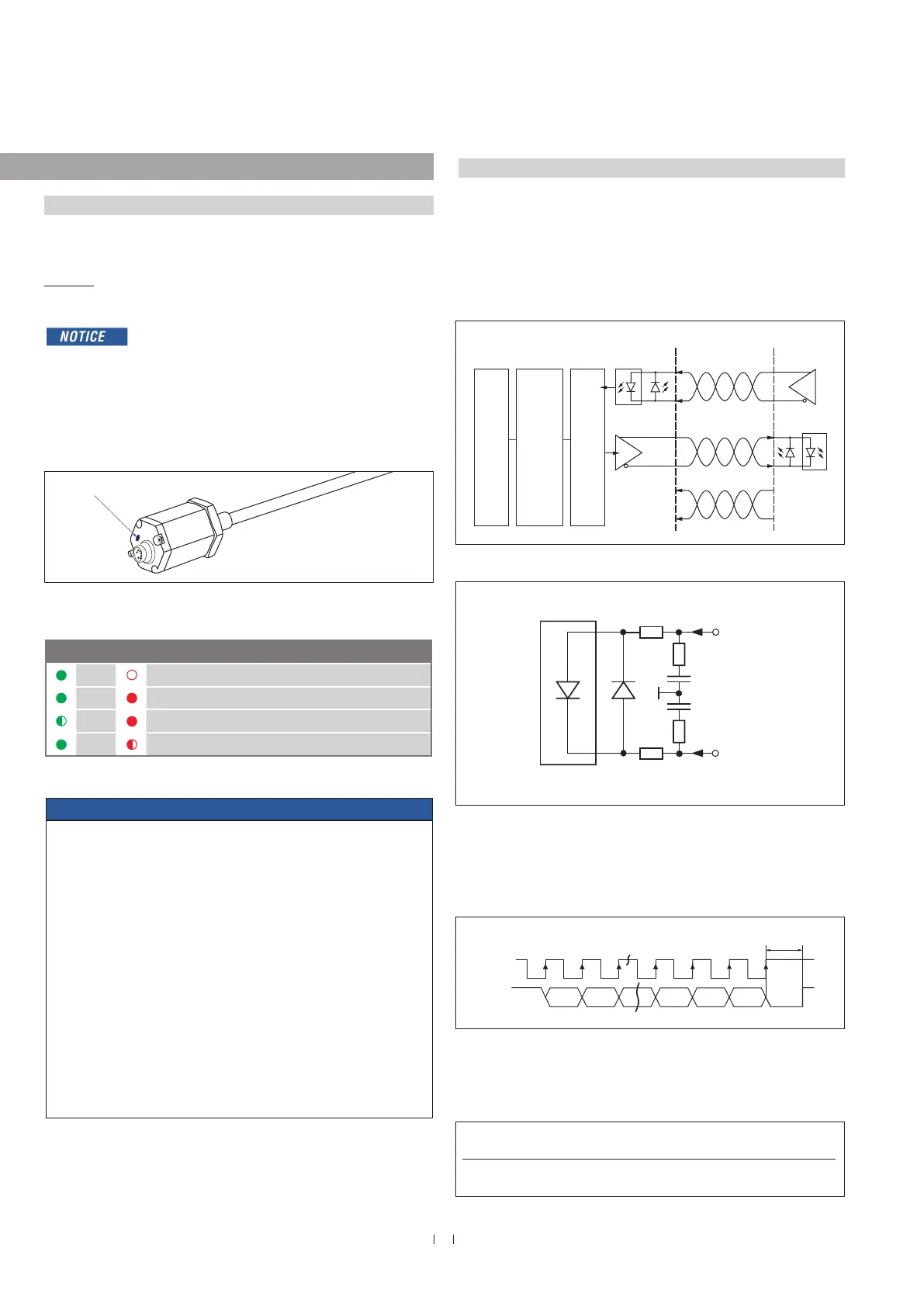
Fig. 52: Schematic connection
Fig. 53: Input wiring clock (+) / clock (−)
Fig. 54: Timing diagram
Fig. 55: Cable lengths and related baud rates
LED status
Green
Red
ON OFF
Normal function
ON ON
No magnet / wrong quantity of magnets
Flashing ON
Programming mode
ON Flashing
Sensor not synchronous*
* for synchronous measurement only
Logic diagram Sensor Controller
Clock (+)
Clock (−)
Optocoupler
Driver
Data (+)
Data (−)
+24 VDC
0 V
ASIC for parallel and
absolute position data
Microprocessor system
position value = 24 / 25 / 26 bit
binary or gray
Shift register
parallel serial converter
91 Ω 7 mA
Clock (+)
100 Ω
LED
1 nF
100 Ω
Clock (−)
91 Ω
2 V
Clock (+)
Data (+)
MSB LSB
Clock interval min. 16 µs
Cable length < 3 m < 50 m < 100 m < 200 m < 400 m
Baud rate 1 MBd < 400 kBd < 300 kBd < 200 kBd < 100 kBd
Status LED

 Loading...