36
Temposonics
®
R-Series SSI
Operation Manual
Temposonics
®
R-Series SSI
Operation Manual
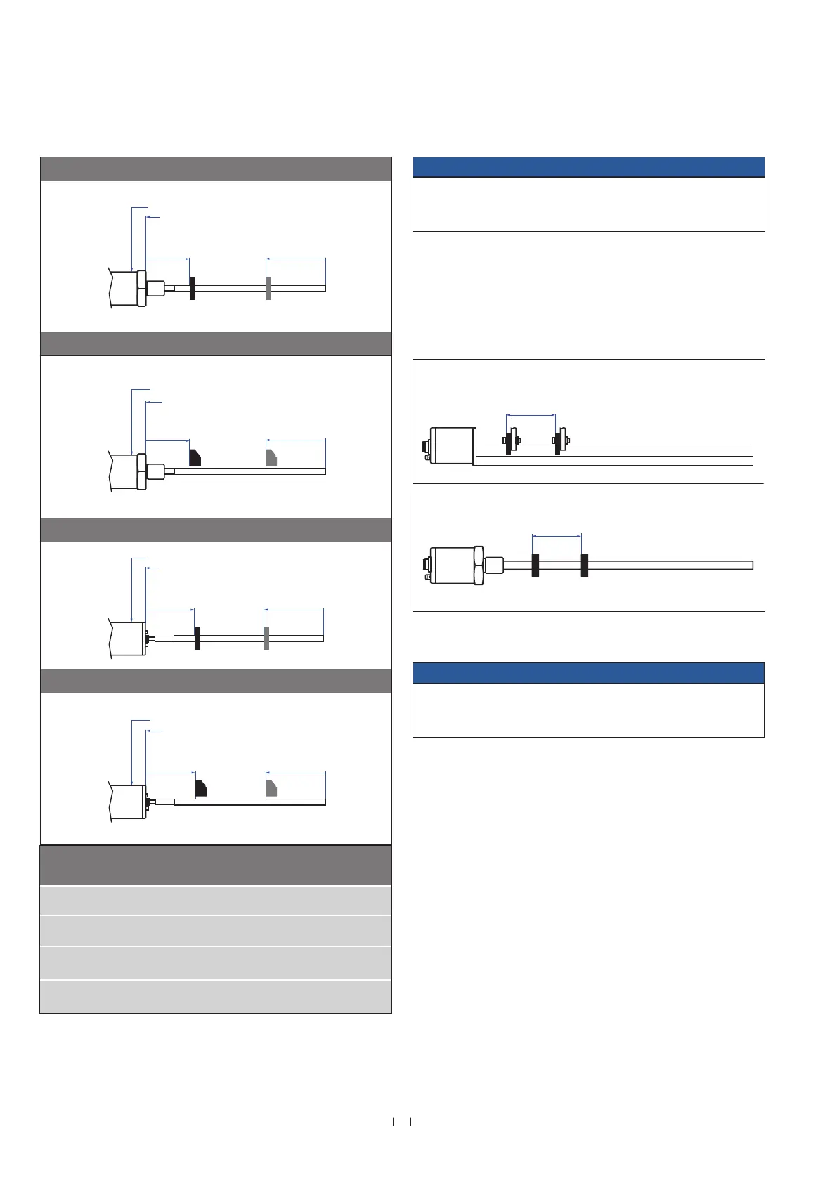
NOTICE
On all sensors, the areas left and right of the active stroke length are
provided for null and dead zone. These zones should not be used for
measurement, however the active stroke length can be exceeded.
RF-M / -S with ring magnet & U-magnet
Sensor electronics housing
Reference edge of mounting
Start position
51 (2.01)
End position
See table
RF-M / -S with block magnet
Sensor electronics housing
Reference edge of mounting
Start position
48.5 (1.91)
End position
See table
RF-C with ring magnet & U-magnet
Sensor electronics housing
Reference edge of mounting
Start position
61 (2.4)
End position
See table
RF-C with block magnet
Sensor electronics housing
Reference edge of mounting
Start position
58.5 (2.3)
End position
See table
Fig. 44: Start- and end positions of magnets (part 2)
Differentiation measurement
For a differentiation measurement two positions are measured on the
sensor rod or sensor profile. The distance between these positions will
be output.
NOTICE
Do not go below a minimal distance of 75 mm (3 in.) between the
magnets for differentiation measurement.
12
Use magnets of the
same type (e.g. two ring magnets) for differentiation measurement.
Fig. 45: Minimum distance between magnets for differentiation measurement
(RP, RH, RD4, RF), example U-magnets (top) and ring magnets (bottom)
Controlling design dimensions are in millimeters and measurements in ( ) are in inches
Stroke length RF End position of
ring magnet /
U-Magnet
Tolerance of total
length
Up to 7620 mm
(300.00 in.)
+8 mm (0.31 in.) /
−5 mm (0.20 in.)
94 mm
(3.70 in.)
Up to 10,000 mm
(393.70 in.)
+15 mm (0.59 in.) /
−15 mm (0.59 in.)
100 mm
(3.94 in.)
Up to 15,000 mm
(590.55 in.)
+15 mm (0.59 in.) /
−30 mm (1.18 in.)
120 mm
(4.72 in.)
Up to 20,000 mm
(787.00 in.)
+15 mm (0.59 in.) /
−45 mm (1.77 in.)
140 mm
(5.51 in.)
End position of
block magnet
96.5 mm
(3.8 in.)
102.5 mm
(4.04 in.)
122.5 mm
(4.82 in.)
142.5 mm
(5.61 in.)
12/ Contact MTS Sensors if you need a magnet distance, which is smaller than 75 mm (3 in.).
For rod versions (e.g. with ring magnets)
For profile versions (e.g. with U-magnets)
≥ 75
(≥ 3)
≥ 75
(≥ 3)

 Loading...