33
Temposonics
®
R-Series SSI
Operation Manual
Temposonics
®
R-Series SSI
Operation Manual
Notice for metric threaded flanges
For additional information about optional accessories see:
• HFP profile (document part number: 551442)
• Pressure rod HD / HL / HP (document part number: 551770)
Note the following points when using a RF-M / -S sensor
respectively pressure rod HD / HL / HP:
• Note the fastening torque of 50 Nm.
• Seat the flange contact surface completely on the cylinder mounting
surface.
• The cylinder manufacturer determines the pressure-resistant gasket
(copper gasket, O-ring, etc.).
• The position magnet should not grind on the sensor rod.
• The piston rod drilling for RF sensors with pressure rod (outer
diameter 12.7 mm (0.5 in.)) is ≥ 16 mm (≥ 0.63 in.). The borehole
depends on the pressure and piston speed.
• Adhere to the information relating to operating pressure.
• Protect the sensor rod against wear.
4.7 Magnet installation
NOTICE
Mount ring magnets and U-magnets concentrically.
Mount block magnets centrically over the sensor rod or the sensor
profile.
Do not exceed the maximum acceptable gap (Fig. 39 / Fig. 40).
Typical use of magnets
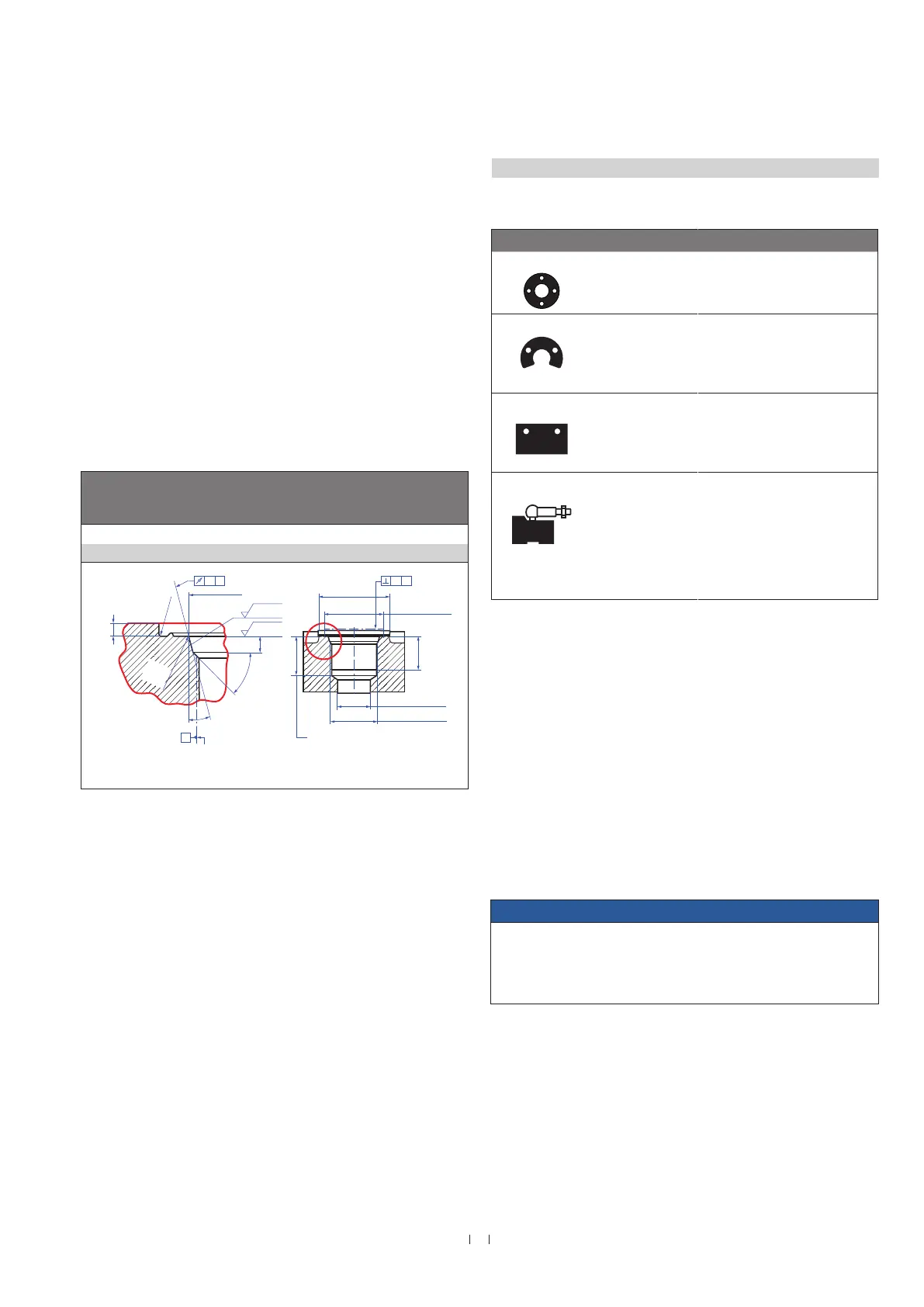
Mounting ring magnets, U-magnets & block magnets
Install the magnet using non-magnetic material for mounting
device, screws, spacers etc.. The magnet must not grind on
the sensor rod. Alignment errors are compensated via the air gap.
• Permissible surface pressure: Max. 40 N/mm
2
(only for ring
magnets and U-magnets)
• Fastening torque for M4 screws: 1 Nm; use washers, if necessary
• Minimum distance between position magnet and any magnetic
material has to be 15 mm (0.6 in.) (Fig. 41).
• If no other option exists and magnetic material is used, observe the
specified dimensions (Fig. 41).
Magnet Typical sensors Benefits
Ring magnets
Rod models
(RH, RD4, RT4,
RF)
• Rotationally symmetrical
magnetic field
U-magnets
Profile &
rod models
(RP, RH, RD4,
RT4, RF)
• Height tolerances can be
compensated
Block magnets
Profile &
rod models
(RP, RH, RF)
• The magnet can be lifted off
• Height tolerances can
be compensated
Magnet sliders
Profile models
(RP)
• The magnet is guided
through the profile
• The distance between the
magnet and the waveguide
is strictly defined
• Easy coupling via the
ball joint
Fig. 37: Notice for metric threaded flange M18×1.5-6g based on DIN ISO 6149-1
Fig. 38: Typical use of magnets
Controlling design dimensions are in millimeters
Thread
(d
1
×P)
d
2
d
3
d
4
d
5
+0.1
0
L
1
+0.4
0
L
2
L
3
L
4
Z°
±1°
RF-M / optional pressure rod HD
M18×1.5-6g 55 ≥ 16 24.5 19.8 2.4 28.5 2 26 15°
Ød
5
Ra 3.2
Ra 3.2
Pitch diameter
A
A
Thread
(d
1
× P)
Ød
3
(Reference)
A
Ød
2
Ød
4
(Gauging)
This dimension applies when
tap drill cannot pass through
entire boss.
≤ R0.4
R0.3
R0.1
Z°
4
5
°
±
5
°
3
L
1
L
2
L
4
A0.1 A0.2

 Loading...