29
Temposonics
®
R-Series SSI
Operation Manual
Temposonics
®
R-Series SSI
Operation Manual
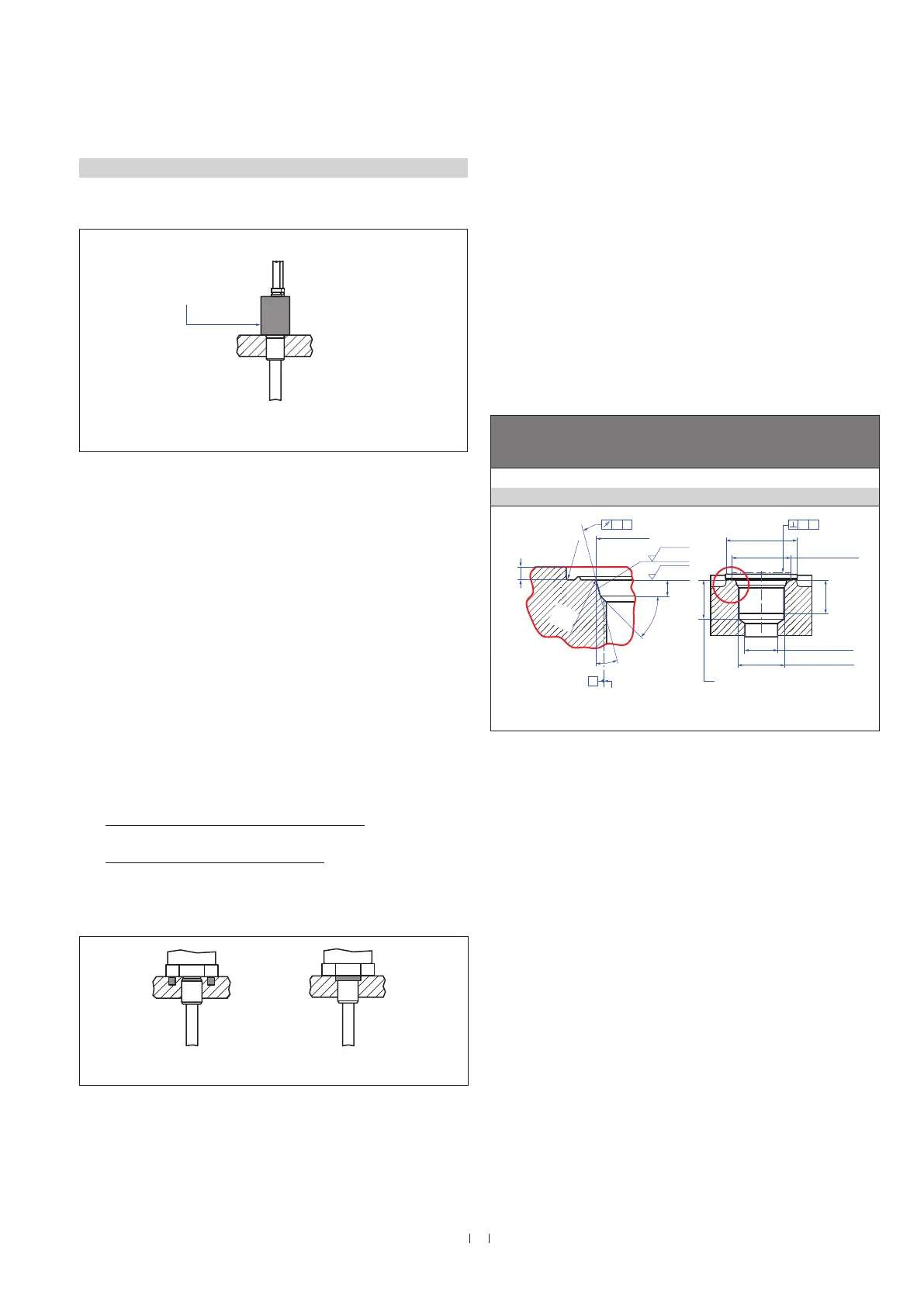
4.5.1 Installation of RT4 with threaded flange
Fix the sensor rod via threaded flange M18×1.5-6g or ¾"-16 UNF-3A.
Hydraulics sealing
There are two ways to seal the flange contact surface (Fig. 27):
1. A sealing by using an O-ring (e.g. 22.4 × 2.65 mm (0.88 × 0.1 in.),
25.07 × 2.62 mm (0.99 × 0.1 in.)) in a cylinder end cap groove.
2. A sealing by using an O-ring in the undercut.
For threaded flange (¾"-16 UNF-3A) »D« / »T«:
O-ring 16.4 × 2.2 mm (0.65 × 0.09 in.) (part no. 560 315)
For threaded flange (M18×1.5-6g) »M«:
O-ring 15.3 × 2.2 mm (0.60 × 0.09 in.) (part no. 401 133)
In this case, a screw hole based on ISO 6149-1 must be provided
(Fig. 28). See ISO 6149-1 for further information.
• Note the fastening torque of 50 Nm.
• Seat the flange contact surface completely on the cylinder mounting
surface.
• The cylinder manufacturer determines the pressure-resistant gasket
(copper gasket, O-ring, etc.).
• The position magnet should not grind on the sensor rod.
• The piston rod drilling (≥ Ø 13 mm (≥ Ø 0.51 in.)) depends on the
pressure and piston speed.
• Adhere to the information relating to operating pressure.
• Protect the sensor rod against wear.
Notice for metric threaded flanges
Fig. 26: Mounting example of threaded flange »D« / M« & »T«
Fig. 27: Possibilities of sealing
Fig. 28: Notice for metric threaded flange M18×1.5-6g based on DIN ISO 6149-1
Controlling design dimensions are in millimeters
Thread
(d
1
×P)
d
2
d
3
d
4
d
5
+0.1
0
L
1
+0.4
0
L
2
L
3
L
4
Z°
±1°
RT4-M
M18×1.5-6g 55 13 24.5 19.8 2.4 28.5 2 26 15°
Ød
5
Ra 3.2
Ra 3.2
Pitch diameter
A
A
Thread
(d
1
× P)
Ød
3
(Reference)
A
Ød
2
Ød
4
(Gauging)
This dimension applies when
tap drill cannot pass through
entire boss.
≤ R0.4
R0.3
R0.1
Z°
4
5
°
±
5
°
3
L
1
L
2
L
4
A0.1 A0.2
Installation of a rod-style sensor in a fluid cylinder
The rod-style version has been developed for direct stroke
measurement in a fluid cylinder. Mount the sensor via threaded flange
or a hex nut.
• Mounted on the face of the piston, the position magnet travels
over the rod without touching it and indicates the exact position
through the rod wall – independent of the hydraulic fluid.
• The pressure resistant sensor rod is installed into a bore in the
piston rod.
Threaded flange »D« / »M«, »T«
Fastening torque
50 Nm
Sealing via O-ring
Sealing via O-ring
in cylinder end cap groove

 Loading...