26
Temposonics
®
R-Series SSI
Operation Manual
Temposonics
®
R-Series SSI
Operation Manual
Mounting of sensor electronics housing
Mount the sensor electronics housing with 4 M6×45 (ISO 4762)
screws via the mounting block. Note the fastening torque of 6 Nm.
Fig. 23: Mounting of RD4‘s sensor electronics housing (example of bottom cable entry)
Connect the flange to the sensor electronics housing via the molex
connectors for bottom cable entry respectively via the 6 pin cable for
side cable entry.
NOTICE
To fulfill the EMC standards for emission and immunity the
following points are necessary:
• The sensor electronics housing has to be connected to machine
ground.
• The cable between the sensor and the electronics must be
integrated into a metallic housing.
Sensor electronics with side cable entry
Connect the rod via the cable to the sensor electronics on the side.
Encapsulate the sensor system including the connection cables
(Fig. 22). Note the bending radius of the cable if you run the cable
between sensor electronics and rod (see Fig. 15).
The following section explains the connection of a RD4 sensor with
bottom cable entry (Fig. 21) and side cable entry (Fig. 22) based on
RD4-S. The sensor electronics of RD4 sensors with threaded flange
are mounted in the same way.
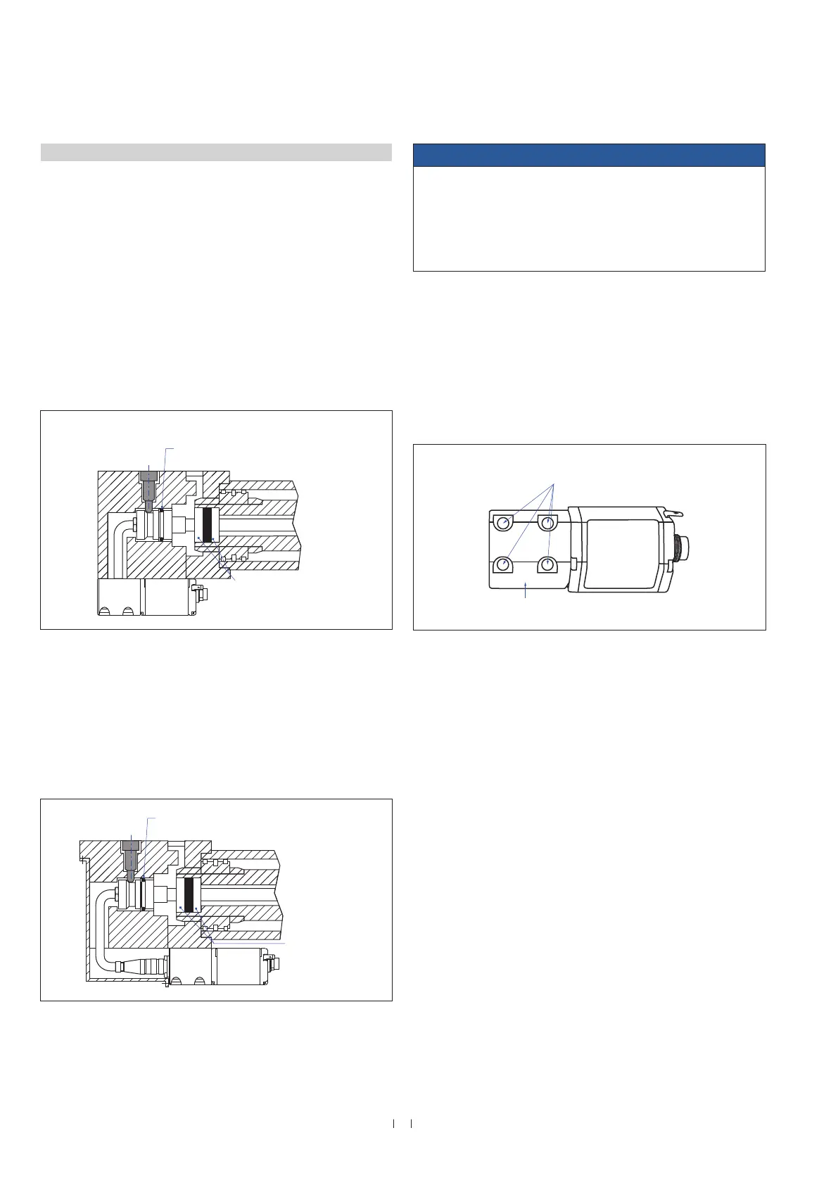
Sensor electronics with bottom cable entry
Connect the rod via the connector to the sensor electronics. Mount the
sensor electronics so that you can lead the cables below the bottom of
the housing. Thus the sensor system including the connection cables
is fully encapsulated and protected against external disturbances
(Fig. 21). Note the bending radius of the cable if you run the cable
between sensor electronics and rod (see Fig. 15).
Fig. 21: Mounting example of pressure fit flange »S« and sensor electronics with bottom
cable entry
Fig. 22: Mounting example of pressure fit flange »S« and sensor electronics with side cable
entry
4.4.3 Installation of RD4’s sensor electronics housing
Controlling design dimensions are in millimeters and measurements in ( ) are in inches
4 M6×45 (ISO 4762) screws
Fastening torque: 6 Nm
Non-magnetic
material
O-ring 21.9 × 2.6 (part no. 560 705)
Back-up ring (part no. 560 629)
Magnet
O-ring 21.9 × 2.6 (part no. 560 705)
Back-up ring (part no. 560 629)
Magnet
Non-magnetic
material

 Loading...