5
Temposonics
®
R-Series SSI
Operation Manual
Temposonics
®
R-Series SSI
Operation Manual
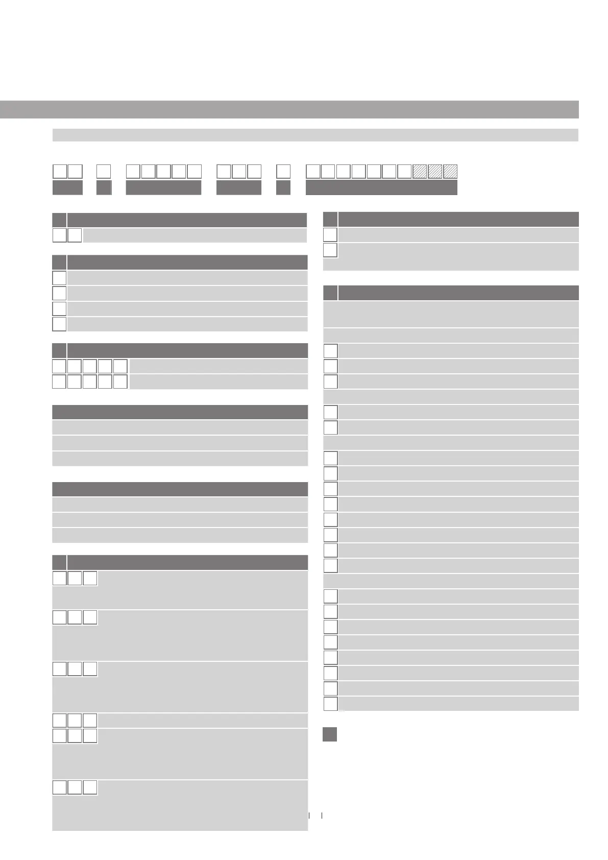
3. Identification
3.1 Order code of Temposonics
®
RP
R P
a b c d e
b Design
G
Magnet slider, joint on top, backlash free (part no. 253 421)
M
U-magnet, OD33 (part no. 251 416-2)
S
Magnet slider, joint on top (part no. 252 182)
V
Magnet slider, joint at front (part no. 252 184)
f Output
S (14) (15) (16) (17) (18) (19) (20) (21) (22)
= Synchronous Serial Interface
Data length (box no. 14)
1
25 bit
2
24 bit
3
26 bit
Output format (box no. 15)
B
Binary
G
Gray
Resolution (box no. 16)
1
0.005 mm
2
0.01 mm
3
0.05 mm
4
0.1 mm
5
0.02 mm
6
0.002 mm
8
0.001 mm
9
0.0005 mm
Filtering performance (box no. 17)
A
No filter + error delay (4 cycles)
C
No filter + error delay (8 cycles)
1
Standard (no filters)
8
Noise reduction filter (8 measurements)
D
No filter + error delay (10 cycles)
G
Noise reduction filter (8 measurements) + error delay (10 cycles)
K
Peak reduction filter (8 measurements)
N
Peak reduction filter (8 measurements) + error delay (10 cycles)
S
f
20, 21, 22: Optional
d Connection type
D 7 0
M16 (7 pin) male connector
See “Frequently ordered accessories” for cable
connector specifications
F
X X
XX m PUR cable (part no. 530 045)
F01…F10 (1…10 m / 3…33 ft.)
3
See “Frequently ordered accessories” for cable
specifications
H
X X
XX m PUR cable (part no. 530 052)
H01…H10 (1…10 m / 3…33 ft.)
3
See “Frequently ordered accessories” for cable
specifications
M S 0
MS0 (10 pin) male connector
P
X
X
XX m TMPU cable (part no. 530 029)
P01…P10 (1…10 m / 3…33 ft.)
3
See “Frequently ordered accessories” for cable
specifications
R
X X
XX m PVC cable (part no. 530 032)
R01…R10 (1…10 m / 3…33 ft.)
3
See “Frequently ordered accessories” for cable
specifications
e Operating voltage
1
+24 VDC (−15 / +20 %)
A
+24 VDC (−15 / +20 %), vibration resistant
(stroke length 25…2000 mm / 1…79 in.)
a Sensor model
R P
Profile
.
c Stroke length
X X X X M
0025…5080 mm
X X X X
U
001.0…200.0 in.
Standard stroke length (mm)*
Stroke length Ordering steps
25 … 500 mm 25 mm
500…2500 mm 50 mm
2500…5080 mm 100 mm
Standard stroke length (in.)*
Stroke length Ordering steps
1 … 20 in. 1 in.
20…100 in. 2 in.
100…200 in. 4 in.
.
*/ Non standard stroke lengths are available; must be encoded in 5 mm / 0.1 in.
increments
3/ Encode in meters if using metric stroke length. Encode in feet if using US customary
stroke length
1 2 3 4 5 6 7 8 9 10 11 12 13 14 15 16 17 18
19 20 21 22
f
Continued on next page

 Loading...