37
Temposonics
®
R-Series SSI
Operation Manual
Temposonics
®
R-Series SSI
Operation Manual
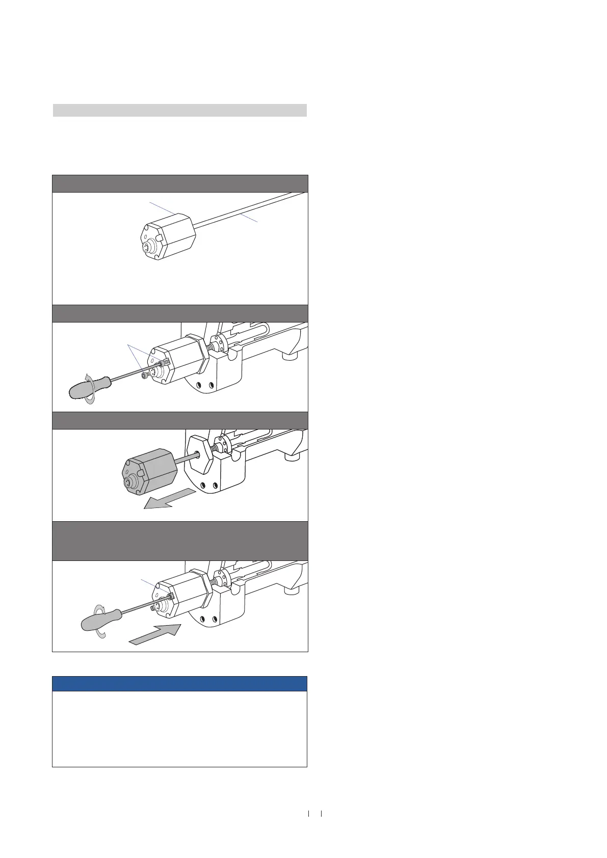
4.8 Replacement of sensor
The base unit of the sensor models RH (RH-B) and RF (RF-C) is
replaceable as shown in Fig. 46. The sensor can be replaced without
interrupting the hydraulic circuit.
NOTICE
• The base unit of the high vibration resistant sensor model RH
cannot be replaced.
• If necessary, the sensor electronics of sensor model RD4 or RT4
can be replaced. Contact MTS Sensors for further information.
• Secure the base unit screws, e.g. using Loctite 243, before
re-installing.
Fig. 46: Replacement of the base unit (e.g. RH sensor)
Base unit
Sensor electronics housing
Plastic tube with
inner sensor element
Note:
The base unit will be delivered without
ground lug. Mount the ground lug at the
base unit. Ground the sensor via the
ground lug.
1. Loosen the screws.
2 × socket head screw
M4 (A/F 2.5)
2. Pull out the base unit.
3. Insert the new base unit.
Install the ground lug on a screw.
Tighten the screws.
Fastening torque: 1.3 Nm

 Loading...