30
Temposonics
®
R-Series SSI
Operation Manual
Temposonics
®
R-Series SSI
Operation Manual
NOTICE
To fulfill the EMC standards for emission and immunity the
following points are necessary:
• The sensor electronics housing has to be connected to machine
ground.
• The cable between the sensor and the electronics must be
integrated into a metallic housing.
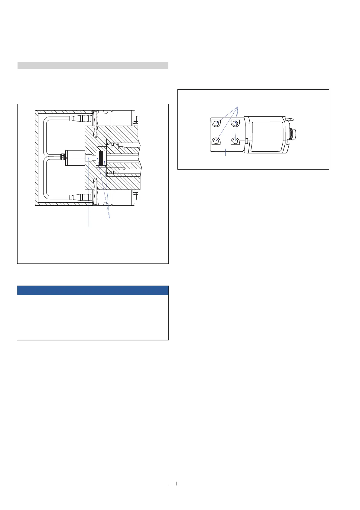
Mounting of sensor electronics housing
Mount the sensor electronics housing with 4 M6×45 (ISO 4762)
screws via the mounting block. Note the fastening torque of 6 Nm.
Fig. 30: Mounting of RT4‘s sensor electronics housing
Connect the flange to the sensor electronics housing via the 6 pin
cable.
Fig. 29: Mounting example of RT4
4.5.2 Installation of RT4’s sensor electronics housing
Connect the rod via the cable to the sensor electronics on the side.
Encapsulate the sensor system including the connection cables
(Fig. 29).
Controlling design dimensions are in millimeters and measurements in ( ) are in inches
4 M6×45 (ISO 4762) screws
Fastening torque: 6 Nm
Magnet
Threaded flange (¾"-16 UNF-3A):
O-ring 16.4 × 2.2 (0.65 × 0.09)
(part no. 560 315)
Threaded flange (M18×1.5-6g):
O-ring 15.3 × 2.2 (0.6 × 0.09 )
Non-magnetic material

 Loading...