28
Temposonics
®
R-Series SSI
Operation Manual
Temposonics
®
R-Series SSI
Operation Manual
NOTICE
II
+
I
+
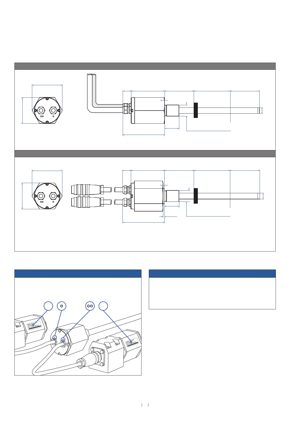
Note for installation respectively for replacement
The position measurement is erroneous, if the
sensor will not be connected as shown!
Fig. 25: Temposonics
®
RT4 flanges with ring magnet
NOTICE
Mount the sensor as follows:
1. Mount the flange with sensor rod
2. Mount the sensor electronics housing
3. Connect the cable between flange and the sensor electronics
housing
The steps mentioned above will be explained in chapter 4.5.1 and
chapter 4.5.2.
Threaded flange with flat-face »D« / »M«
7.7
(0.3)
24.7
(0.97)
24.7
(0.97)
Sensor electronics housing
70
(2.8)
50
(1.97)
45
(1.78)
14
(0.5)
57
(2.2)
25
(0.98)
Null zone
51
(2.01)
Stroke length
25…2540
(1…100)
Dead zone
64
(2.5)
71
(2.8)
Ø 10
(Ø 0.39)
44.5
(1.75)
51
(2.01)
44.5
(1.75)
51
(2.01)
Sensor
electronics
housing
45
(1.8)
49
(1.9)
41
(1.6 )
45
(1.8)
49
(1.9)
41
(1.6 )
Side view
(second sensor electronics not shown)
Magnet
Recommendation:
Use M6×45 (ISO 4762) screws for sensor fastening.
Fastening torque: 6 Nm
14
(0.5)
57
(2.2)
25
(0.98)
71
(2.8)
Null zone
51
(2.01)
2.5
(0.10)
Stroke length
25…2540
(1…100)
Dead zone
64
(2.5)
Ø 10
(Ø 0.39)
Magnet
Flange »D«: ¾"-16 UNF-3A
Flange »M«: M18×1.5-6g
50
(1.97)
Mounting block
45 (1.8)
Mounting block
45 (1.8)
45
(1.78)
Sensor electronics housing
62
(2.44)
Side view
(second sensor electronics not shown)
Recommendation:
Use M6×45 (ISO 4762) screws for sensor fastening.
Fastening torque: 6 Nm
7.7
(0.3)
24.7
(0.97)
24.7
(0.97)
Sensor
electronics
housing
26
(1.02)
Ø 6.2
(Ø 0.24)
Ø 6.2
(Ø 0.24)
8.2
(0.32)
8.2
(0.32)
12
(0.46)
23
(0.91)
Ø 18
(Ø 0.7)
38
(1.5)
23
(0.91)
Ø 18
(Ø 0.7)
A/F 44.5
Threaded flange with raised-face »T«
7.7
(0.3)
24.7
(0.97)
24.7
(0.97)
Sensor electronics housing
70
(2.8)
50
(1.97)
45
(1.78)
14
(0.5)
57
(2.2)
25
(0.98)
Null zone
51
(2.01)
Stroke length
25…2540
(1…100)
Dead zone
64
(2.5)
Flange »T«: ¾"-16 UNF-3A
71
(2.8)
Ø 10
(Ø 0.39)
38
(1.5)
44.5
(1.75)
51
(2.01)
44.5
(1.75)
51
(2.01)
Sensor
electronics
housing
45
(1.8)
49
(1.9)
41
(1.6 )
45
(1.8)
49
(1.9)
41
(1.6 )
Side view
(second sensor electronics not shown)
Magnet
Recommendation:
Use M6×45 (ISO 4762) screws for sensor fastening.
Fastening torque: 6 Nm
14
(0.5)
57
(2.2)
25
(0.98)
71
(2.8)
Null zone
51
(2.01)
2.5
(0.10)
Stroke length
25…2540
(1…100)
Dead zone
64
(2.5)
Ø 10
(Ø 0.39)
Magnet
Flange »D«: ¾"-16 UNF-3A
Flange »M«: M18×1.5-6g
50
(1.97)
Mounting block
45 (1.8)
Mounting block
45 (1.8)
45
(1.78)
Sensor electronics housing
62
(2.44)
Side view
(second sensor electronics not shown)
Recommendation:
Use M6×45 (ISO 4762) screws for sensor fastening.
Fastening torque: 6 Nm
7.7
(0.3)
24.7
(0.97)
24.7
(0.97)
Sensor
electronics
housing
26
(1.02)
Ø 6.2
(Ø 0.24)
Ø 6.2
(Ø 0.24)
8.2
(0.32)
8.2
(0.32)
12
(0.46)
23
(0.91)
Ø 18
(Ø 0.7)
38
(1.5)
23
(0.91)
Ø 18
(Ø 0.7)
A/F 44.5
A/F 44.5
Controlling design dimensions are in millimeters and measurements in ( ) are in inches
Flanges

 Loading...