32
Temposonics
®
R-Series SSI
Operation Manual
Temposonics
®
R-Series SSI
Operation Manual
NOTICE
Connect the sensor electronics housing to machine ground to fulfill
the EMC standards for emission and immunity.
Hydraulics sealing when using a RF sensor in a pressure rod
HD / HL / HP
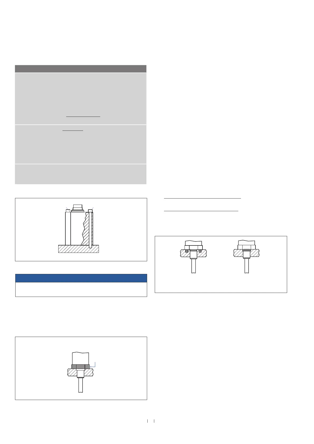
There are two ways to seal the flange contact surface (Fig. 36):
1. A sealing by using an O-ring (e.g. 22.4 × 2.65 mm (0.88 × 0.1 in.),
25.07 × 2.62 mm (0.99 × 0.1 in.)) in a cylinder end cap groove.
2. A sealing by using an O-ring in the undercut.
For threaded flange (¾"-16 UNF-3A) »S«:
O-ring 16.4 × 2.2 mm (0.65 × 0.09 in.) (part no. 560 315)
For threaded flange (M18×1.5-6g) »M«:
O-ring 15.3 × 2.2 mm (0.60 × 0.09 in.) (part no. 401 133)
In this case, a screw hole based on ISO 6149-1 must be provided
(Fig. 37). See ISO 6149-1 for further information.
This is the way you mount the RF sensors:
Sensor design Mounting
RF-C • Insert the flexible sensor rod in a support
tube.
• Mount the sensor electronics housing by
means of 2 non-magnetic socket head
screws M4×59. Fastening torque: 2 Nm
(see Fig. 34)
Recommendation:
Seal the sensor via flange.
RF-C with pressure
rod HD / HL / HP
or HFP profile
(see “Frequently or-
dered accessories”)
Advantage: The flexible sensor rod is inser-
ted in a support tube.
• Mount the sensor electronics housing by
means of 2 non-magnetic socket head
screws M4×59.
Fastening torque: 2 Nm (see Fig. 34)
RF-M / RF-S • Insert the flexible sensor rod in a support
tube.
• Mount the sensor via flange.
Installation of RF with threaded flange »M«, »S« or RF with pressure
rod HD / HL / HP
Fix the sensor rod via threaded flange M18×1.5-6g or ¾"-16 UNF-3A.
Fig. 34: Mounting with socket head screws M4×59
Fig. 35: Mounting example of threaded flange »M«, »S« or pressure rod HD / HL / HP
Fig. 36: Possibilities of sealing
Installation of a RF sensor with pressure rod HD / HL / HP
in a fluid cylinder
The rod-style version has been developed for direct stroke
measurement in a fluid cylinder. Mount the sensor via threaded flange
or a hex nut.
• Mounted on the face of the piston, the position magnet travels
over the rod without touching it and indicates the exact position
through the rod wall – independent of the hydraulic fluid.
• The pressure resistant sensor rod is installed into a bore in the
piston rod.
• The base unit is mounted by means of only 2 screws. It is the
only part that needs to be replaced if servicing is required, i.e. the
hydraulic circuit remains closed. For more information see chapter
“4.8 Replacement of sensor” on page 37.
Socket head screw
M4×59
Socket head screw
M4×59
Fastening torque of socket head screw M4×59: 2 Nm
Sealing via O-ring
Sealing via O-ring
in cylinder end cap groove
50 Nm

 Loading...