34
Temposonics
®
R-Series SSI
Operation Manual
Temposonics
®
R-Series SSI
Operation Manual
Sensors with stroke lengths ≥ 1 meter (3.3 ft.)
Support horizontally installed sensors with a stroke length from 1 meter
(3.3 ft.) mechanically at the rod end. Without the use of a support, rod
and posi tion magnet may be damaged. A false measurement result
is also possi ble. Longer rods require evenly distributed mechanical
support over the entire length (e.g. part no. 561 481). Use an U-magnet
(Fig. 42) for measurement.
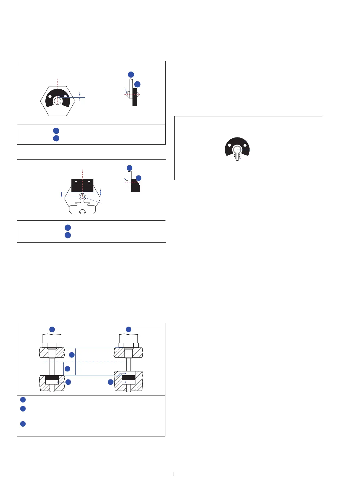
Magnet mounting with magnetic material
When using magnetic material the dimensions of Fig. 41 must
be observed.
A. If the position magnet aligns with the drilled piston rod
B. If the position magnet is set further into the drilled piston rod, install
another non-magnetic spacer (e.g. part no. 400 633) above the
magnet.
Fig. 39: Mounting of U-magnet (part no. 251 416-2 or part no. 201 553)
Fig. 40: Mounting of block magnet (part no. 403 448)
Fig. 41: Installation with magnetic material
Fig. 42: Example of sensor support (part no. 561 481)
Controlling design dimensions are in millimeters and measurements in ( ) are in inches
U-magnet
Sensor rod
Non-magnetic fixing clip
M4
1
2
Air gap
Concentric mounting
of U-magnet
Part no. 201 553:
3 ±1 (0.12 ±0.04)
Part no. 251 416-2:
1.75 ±1 (0.07 ±0.04)
U-magnet
Non-magnetic mounting plate
1
2
M4
2
1
8 ±2
(0.31 ±0.08)
Sensor element
Air gap: 3 ±2
(0.12 ±0.08)
Block magnet
Non-magnetic mounting plate
1
2
Magnet
Magnet
1
2
3 3
Magnetic
material
1
Null zone, depends on sensor model (see Fig. 43 / Fig. 44)
2
Distance between position magnet and any magnetic material
(≥ 15 mm (≥ 0.6 in.))
3
Non-magnetic spacer (≥ 5 mm (≥ 0.2 in.)) –
Recommendation: 8 mm (0.31 in.)

 Loading...