35
Temposonics
®
R-Series SSI
Operation Manual
Temposonics
®
R-Series SSI
Operation Manual
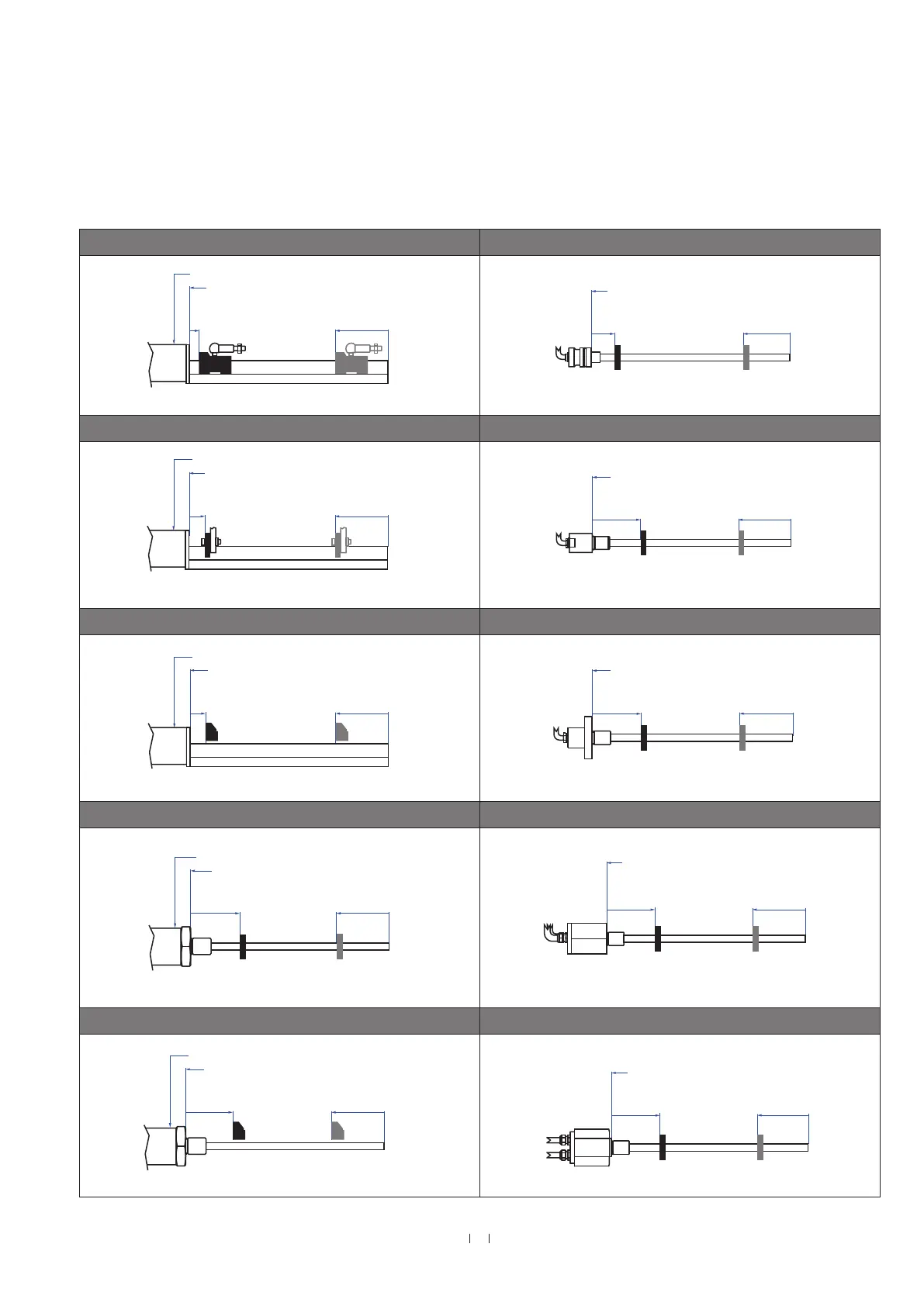
Start- and end positions of the position magnets
Consider the start and end positions of the position magnets during
the installation.
Controlling design dimensions are in millimeters and measurements in ( ) are in inches
Fig. 43: Start- and end positions of magnets (part 1)
RP with magnet slider “S”, “N”, “V”, “G” RD4-S with ring magnet & U-magnet
Sensor electronics housing
Reference edge of mounting
Start position
12 (0.47)
End position
82 / 87* (3.23 / 3.43*)
* Stroke length > 5000 mm (196.9 in.)
Reference edge of mounting
Start position
21.4 (0.84)
63.5 (2.5)
RP with U-magnet RD4-M / -T / -G with ring magnet & U-magnet
Reference edge of mounting
Sensor electronics housing
Start position
28 (1.1)
End position
* Stroke length > 5000 mm (196.9 in.)
Reference edge of mounting
Start position
51 (2.01)
End position
63.5 / 66* (2.5 / 2.6*)
* Stroke length > 5000 mm (196.9 in.)
RP with block magnet RD4-C / -D with ring magnet & U-magnet
Reference edge of mounting
Sensor electronics housing
* Stroke length > 5000 mm (196.9 in.)
End position
68.5 / 73.5* (2.7 / 2.9*)
Start position
25.5 (1)
End position
63,5 / 66*
Reference edge of mounting
Start position
51 (2.01)
* Stroke length > 5000 mm (196.9 in.)
RH with ring magnet & U-magnet RT4-D / -M with ring magnet & U-magnet
Sensor electronics housing
Reference edge of mounting
Start position
51 (2.01)
End position
63.5 / 66* (2.5 / 2.6*)
* Stroke length > 5000 mm (196.9 in.)
Reference edge of mounting
Start position
51 (2.01)
64 (2.52)
RH with block magnet RT4-T with ring magnet & U-magnet
Sensor electronics housing
Reference edge of mounting
Start position
48.5 (1.91)
End position
66 / 68.5* (2.6 / 2.7*)
* Stroke length > 5000 mm (196.9 in.)
Reference edge of mounting
Start position
51 (2.01)
64 (2.52)
To ensure that the entire stroke length is electrically usable, the
position magnet must be mechanically mounted as follows.

 Loading...