Maintenance and servicing
Technical specifications
8
Copyright © Müller-Elektronik GmbH & Co.KG 49
Pin no.: Signal
3 /TxD
4 Operating voltage minus 0.7 volt
5 GND
6 DSR
7 RTS
8 CTS
9 RI
When switched on, the terminal routes current to the farm equipment that is connected via the RS232
connector. The voltage of the RS232 connector is dependent on the operating voltage of the terminal.
When connected to a 12 V battery, the terminal will transfer approx. 11.3 V to the connected
equipment.
When connected to a 24 V battery, the terminal will transfer approx. 23.3 V to the connected
equipment.
The use of a GPS Receiver only requires the signals RxD and TxD as well as GND.
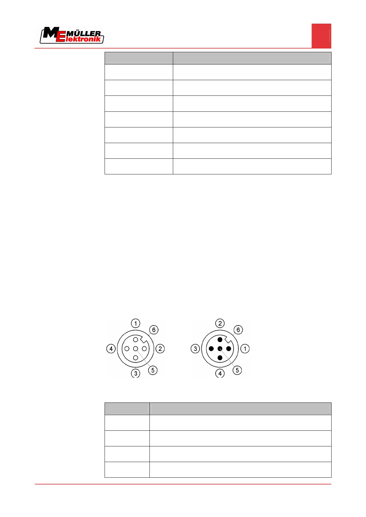
Pin assignment of camera ports 1 and 2
Ports 1 and 2 are used to connect an analogue camera. The pin assignment is identical for both
ports.
Ports 1 and 2 are 5-pin, A-encoded M12 sockets. Please refer to the following table for the pin
assignment.
Pin assignment of the socket (in
the terminal)
Pin assignment of the connector
Pin Signal
1 Pin is exclusively intended for use by ME (do not connect anything)
2 GND
3 Pin is exclusively intended for use by ME (do not connect anything)
4 Video signal
8.4.4