Do you have a question about the Muller Elektronik TRACK Guide II and is the answer not in the manual?
General safety guidelines for operating the terminal and avoiding hazards.
Explains warning symbols and signal words used in the manual for hazard communication.
Specifies prerequisites for operating the terminal correctly and safely, including reading instructions.
Defines the authorized application areas and limitations for the terminal's use in agriculture.
States compliance with relevant EMC directives and harmonized standards for the product.
Identifies the intended audience for this manual, focusing on installation and operation personnel.
Explains the structure and symbols used in the manual for clarity and step-by-step guidance.
Details how cross-references are presented in the document, using brackets and arrows for navigation.
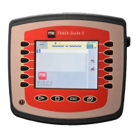
Details the hardware and software capabilities of the TRACK-Guide II terminal, including available applications.
Lists all items included in the package with the terminal, such as cables and documentation.
Explains the details found on the terminal's nameplate and their meaning for product identification.
Provides step-by-step instructions for physically installing the terminal securely inside the tractor cab.
Identifies and explains the function of each connection port on the rear of the terminal.
Instructions on how to properly mount the GSM antenna for optimal radio signal reception.
Details the process of connecting the terminal to the vehicle's electrical system for power.
Explains how to establish an ISOBUS connection for integration with job computers.
Information on the SIM card requirements and selection for utilizing the farmpilot portal.
Step-by-step guide for safely inserting the SIM card into its slot on the terminal.
Instructions for connecting an ISO printer to the terminal for printing ISO-XML task data.
Guide for connecting the ME LightBar for visual parallel guidance assistance.
How to connect external on-board computers using serial interfaces for data exchange.
Instructions for connecting the GPS receiver for obtaining accurate location and navigation data.
Explains how to connect various vehicle sensors via port B for data input.
Guide for connecting an external analogue camera to the terminal for visual monitoring.
Overview of the terminal's physical controls like rotary knob and function keys, and their basic operations.
Step-by-step guide for the first-time power-on and initial setup of the terminal.
Outlines the general order of essential settings and configurations required for terminal operation.
Explains how to operate the terminal by utilizing the function keys and their corresponding on-screen icons.
Procedure for safely restarting the terminal, ensuring connected job computers also restart.
Describes the process of entering data using the on-screen keyboard and input methods.
Guidance on configuring multiple terminals to ensure communication and data synchronization between them.
Explains the visual structure of the application selection screen, including sections and icons.
How to launch different software applications from the main selection menu on the terminal.
How to split the terminal screen to display multiple applications simultaneously for multitasking.
Details the input methods, rotary knob, and function buttons used within the Service application.
Explains the meaning of various icons displayed in the Service application for status and function indication.
Instructions on how to set the display language for the terminal and all applications.
Covers initial configurations like language, time, and measurement units affecting the terminal and job computers.
Information on activating and configuring the connected GPS receiver for accurate positioning.
Steps to select and activate the correct driver for the connected GPS receiver.
Details how to set up parameters like correction signals for compatible GPS receivers.
How to set up terrain compensation features for the GPS TILT-Module for accurate measurements.
Steps to activate the driver for an external ME LightBar for visual guidance display.
Information on activating and operating the connected external camera for visual monitoring.
Steps to select and activate the correct driver for the connected camera.
Explains how to control camera functions like switching views, zooming, and activation modes.
How to assign functions to joystick buttons for ISOBUS job computers, adhering to Auxiliary 2 specifications.
How to change display brightness settings for optimal visibility in day or night conditions.
How to activate or deactivate installed software applications (plug-ins) from the selection menu.
Steps to enter activation numbers to unlock full functionality of pre-installed software applications.
Options for configuring the terminal's role, such as "Login as ISOBUS-UT" or "Run as auxiliary terminal".
How to remove files, like screenshots or task data, from the USB drive connected to the terminal.
How to clear temporary data pools to optimize terminal performance and speed.
How to enable the diagnostics feature for system troubleshooting and information gathering.
Information about capturing and saving screen images for documentation or error reporting.
Settings for enabling and managing the screenshot feature, including storage location.
Step-by-step instructions on how to capture a screenshot using button combinations.
How to configure the CAN-Trace function for logging data exchange for diagnostic purposes.
Overview of setting up the farmpilot portal connection, including required steps.
Steps to activate the driver for the farmpilot portal to enable data exchange.
Details on entering access data like username and password for the farmpilot portal.
Guide for manual GPRS connection setup when automatic configuration fails for mobile data.
How to transmit diagnostic data to the farmpilot portal for detailed examination by customer services.
Steps to activate the driver for the ISO printer to enable printing of task information.
How to create and manage vehicle profiles to store specific tractor and implement settings.
Details on setting up sensors, speed, and working position within a vehicle profile.
Procedure for calibrating the speed sensor using the 100m method for accurate speed measurements.
How to configure the working position sensor type (analog, digital, ME-sensor) and its settings.
Instructions on inputting the GPS receiver's precise location relative to the tractor for accurate navigation.
Steps to activate a previously configured vehicle profile to apply its settings to the current operation.
Overview of the ISOBUS-TC application and its role in managing tasks and data exchange.
How to set up ISOBUS-TC for work with or without ISO-XML tasks, affecting data flow.
How to define the ISOBUS job computers connected to the terminal for accurate data transfer.
How to transfer target rates to an on-board computer using the LH5000 protocol.
How to use the ASD protocol for section control and transferring target rates to on-board computers.
How to use the File Server to define a save location for data like protocols or error messages.
Instructions for routine cleaning and care of the terminal using a soft, damp cloth.
Environmental guidelines for the proper disposal of the terminal as electronic scrap according to EU legislation.
Safety and compliance guidelines for adding new electrical or electronic components to farm equipment.
How to find and verify the currently installed software version displayed on the terminal.
Detailed technical data and specifications for the terminal hardware, including electrical and physical parameters.
Lists electrical, physical, environmental specifications, EMC, and power input details of the terminal.
Details the signal pinout for port A, the 9-pin D-sub ISO agricultural machinery interface (CAN).
Details the signal pinout for port B, which varies based on the terminal's hardware version.
Details the signal pinout for port C, which is an RS232 interface.
Details the signal pinout for the 5-pin M12 sockets used for connecting analogue cameras.
| Brand | Muller Elektronik |
|---|---|
| Model | TRACK Guide II |
| Category | Touch terminals |
| Language | English |