Maintenance and servicing
Technical specifications
12
30302710-02-EN V7.20141016 77
2)
is compliant with TBC_Pwr in ISO 11783. When the terminal is switched on, this pin is under
voltage (supply voltage minus approx. 1.2V).
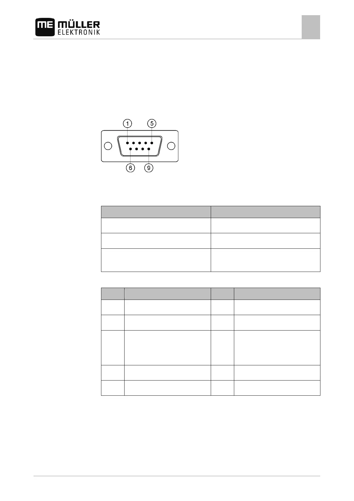
Pin assignment of port B
The pin assignment of port B is dependent on the hardware version of the terminal.
Terminals with hardware versions from 3.0.0
9-pin. D-Sub connector
Port B is a 9-pin D-Sub port.
The connector can be used for the following purposes depending on its assignment:
As second CAN interface 7, 9
As second serial interface
As signal input for two digital and one analog
1, 5, 6, 8
Pin assignment of port B
1
2
3 /TxD 8 Working position sensor
3
or
Reverse signal for determining the
Voltage supply for GPS receiver
4
Legend:
1
) Digital input as per: ISO 11786:1995 chapter 5.2
2
) Digital input as per: ISO 11786:1995 chapter 5.3
3
) Digital input as per: ISO 11786:1995 chapter 5.5
4
) The pin is switched in parallel with pin 4 by port C. Total loading is 600mA.
 Loading...