Mounting and installation
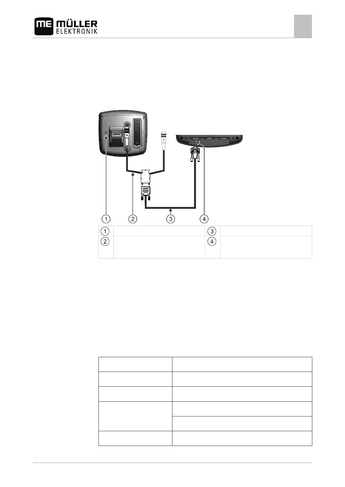
Connecting the GPS Receiver to the terminal
4
30302710-02-EN V7.20141016 17
You can find a list of on-board integrated display/controllers that we have tested here:
▪ Transfer target rates via LH5000 [➙ 69]
▪ Switching sections and transferring target rates via ASD [➙ 70]
For other on-board integrated display/controllers and for on-board integrated display/controllers with
other software versions, this function may not work at all or different from how it is described in these
instructions. Because the operating mode and configuration depends on the on-board integrated
display/controller. You must contact the on-board integrated display/controller manufacturer for this.
On-board computer
Null modem cable
Adapter cable*
Available as a set with Cable 3, item number:
Port B on the terminal
*When using an Amatron3 or Amatron+ as on-board integrated display/controller, you will only need a
traditional null modem cable. (Amatron3 and Amatron+ are on-board integrated display/controller
from Amazone)
Connecting the GPS Receiver to the terminal
Each GPS receiver which is connected to the terminal must fulfil the conditions in the table below.
GPS receivers which can be purchased from Müller Elektronik fulfil these conditions.
Technical requirements for using the DGPS Receiver
Supply voltage of the terminal – 1.5 V
GPS standard NMEA 0183
Refresh rates and signals
1 Hz (GPGSA, GPZDA)
 Loading...