Maintenance and servicing
Technical specifications
12
30302710-02-EN V7.20141016 79
When connected to a 24 V battery, the terminal will transfer approx. 23.3 V to the connected
equipment.
The use of a GPS Receiver only requires the signals RxD and TxD as well as GND.
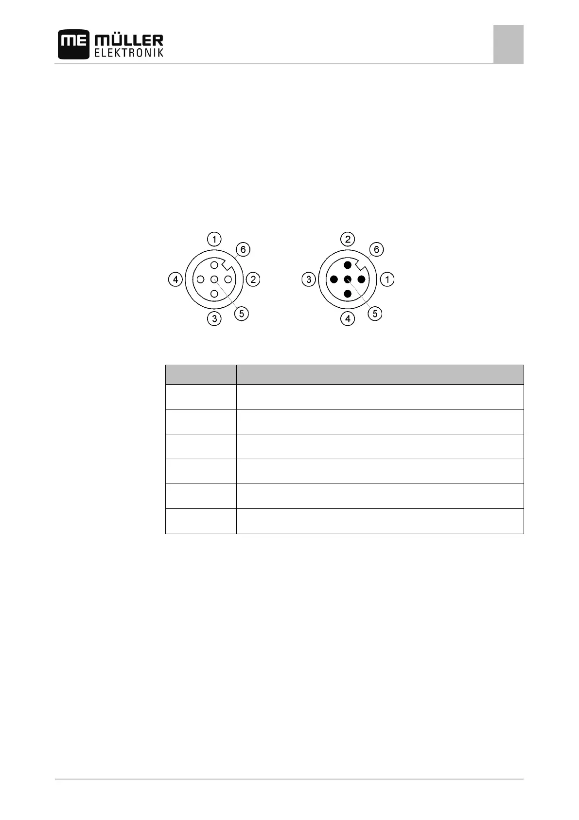
Pin assignment of camera ports 1 and 2
Ports 1 and 2 are used to connect an analogue camera. The pin assignment is identical for both
ports.
Ports 1 and 2 are 5-pin, A-encoded M12 sockets. Please refer to the following table for the pin
assignment.
Pin assignment of the socket (in
Pin assignment of the connector
1 Pin is exclusively intended for use by ME (do not connect anything)
3 Pin is exclusively intended for use by ME (do not connect anything)
Outer sheathing Screen
 Loading...