Virtual ECU application
Parameters
9
To call up the geometry, tap the function icon:
Calls up the machine geometry.
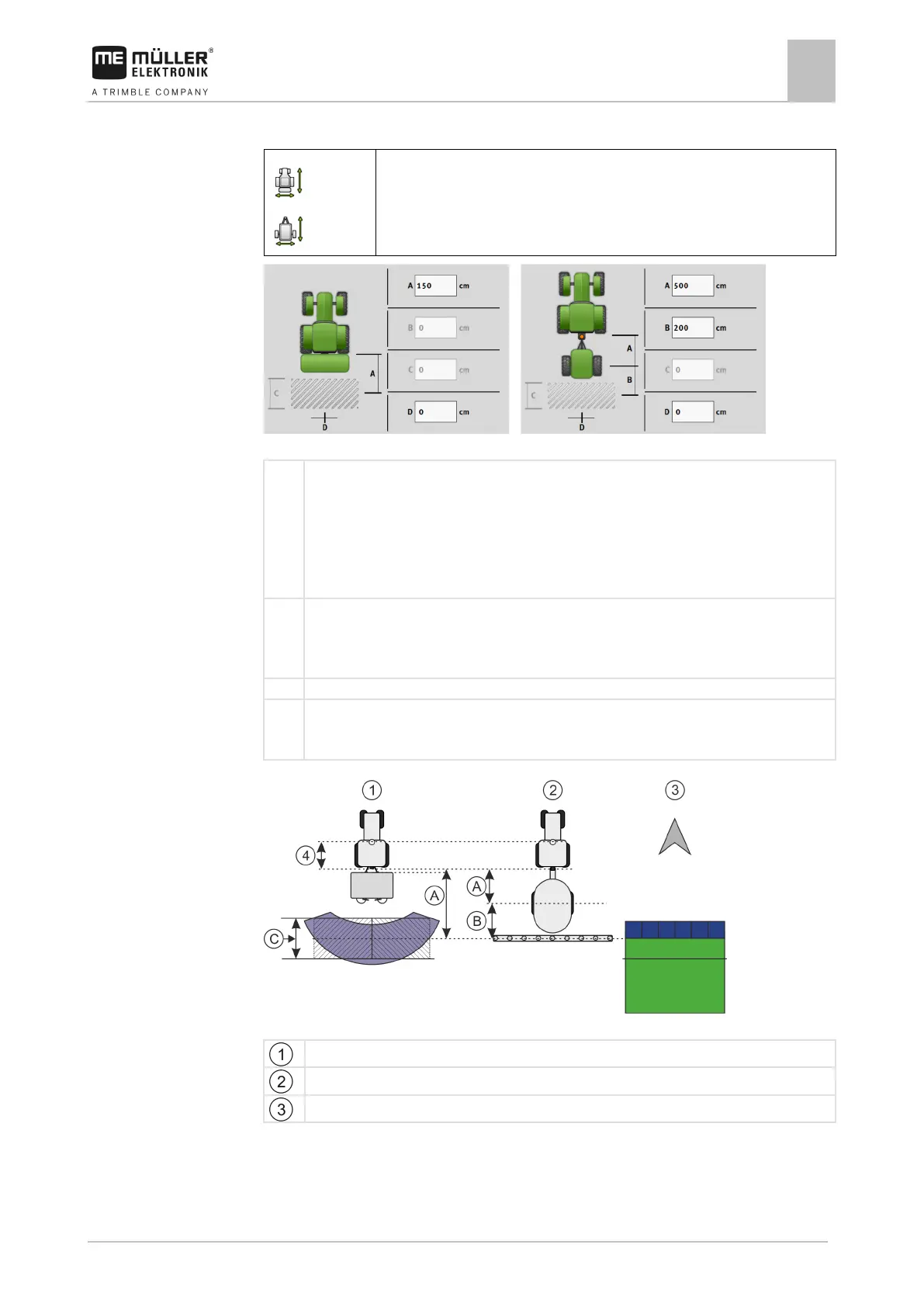
Screen for entering the geometry for different machine models
Distance between the coupling point and the work point of the machine.
Trailed:
Distance between the coupling point and the pivot point of the machine.
For single-axle trailers, the pivot point is located at the centre of the axle, for tandem trailers between
two axles. For planters/seeders, cultivators and other soil tillage implements, the pivot point must be
:
Not available
Trailed:
Distance between the pivot point of the machine and the work point.
Only for spreaders: Working Length
Lateral offset
If the mounted implement is offset to the left in the direction of travel, enter a negative value. For
Geometry of machines and display in TRACK-Leader
Mounted fertilizer spreader
Trailed sprayer
 Loading...