User Manual
User Interface Introduction
1 2 3
13
10
22
20
4 6 7 8
11
9
12
14
1516171819
21
23
5
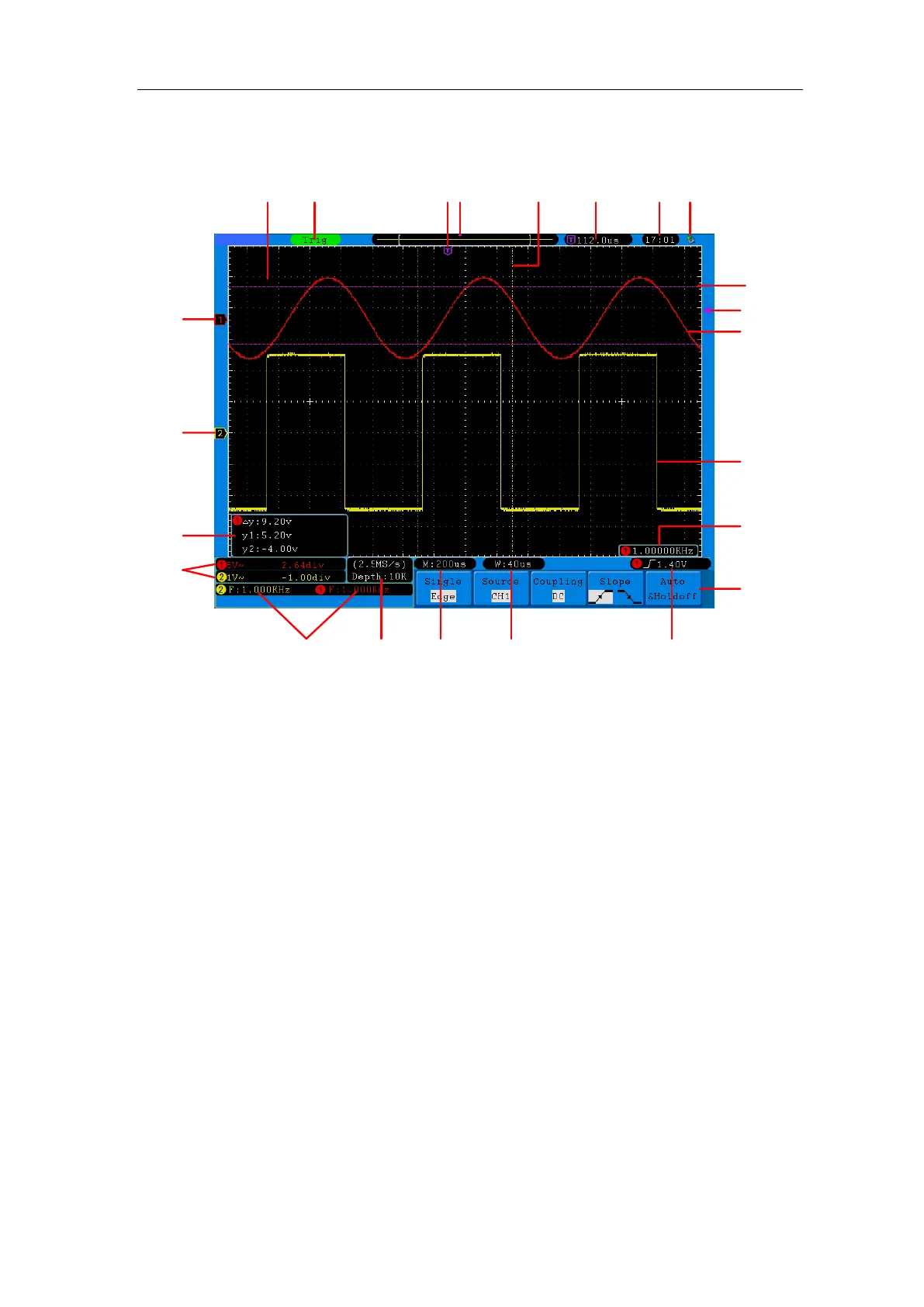
Figure 4-5 Illustrative Drawing of Display Interfaces (SDS5032E(V) shown)
1. Waveform Display Area.
2. The state of trigger, including:
Auto: Automatic mode and acquire waveform without triggering.
Trig: Trigger detected and acquire waveform.
Ready: Pre-triggered data captured and ready for a trigger.
Scan: Capture and display the waveform continuously.
Stop: Data acquisition stopped.
3. The purple T pointer indicates the horizontal position for the trigger.
4. The pointer indicates the trigger position in the internal memory.
5. The two yellow dotted lines indicate the size of the viewing expanded window.
6. It shows present triggering value and displays the site of present window in
internal memory.
7. It shows setting time (see "Config" on P64 ).
8. It indicates that there is a USB disk connecting with the oscilloscope.
9. The waveform of CH1.
10. The purple pointer shows the trigger level position for CH1.
11. The positions of two purple dotted line cursors measurements.
12. The waveform of CH2.