User Manual
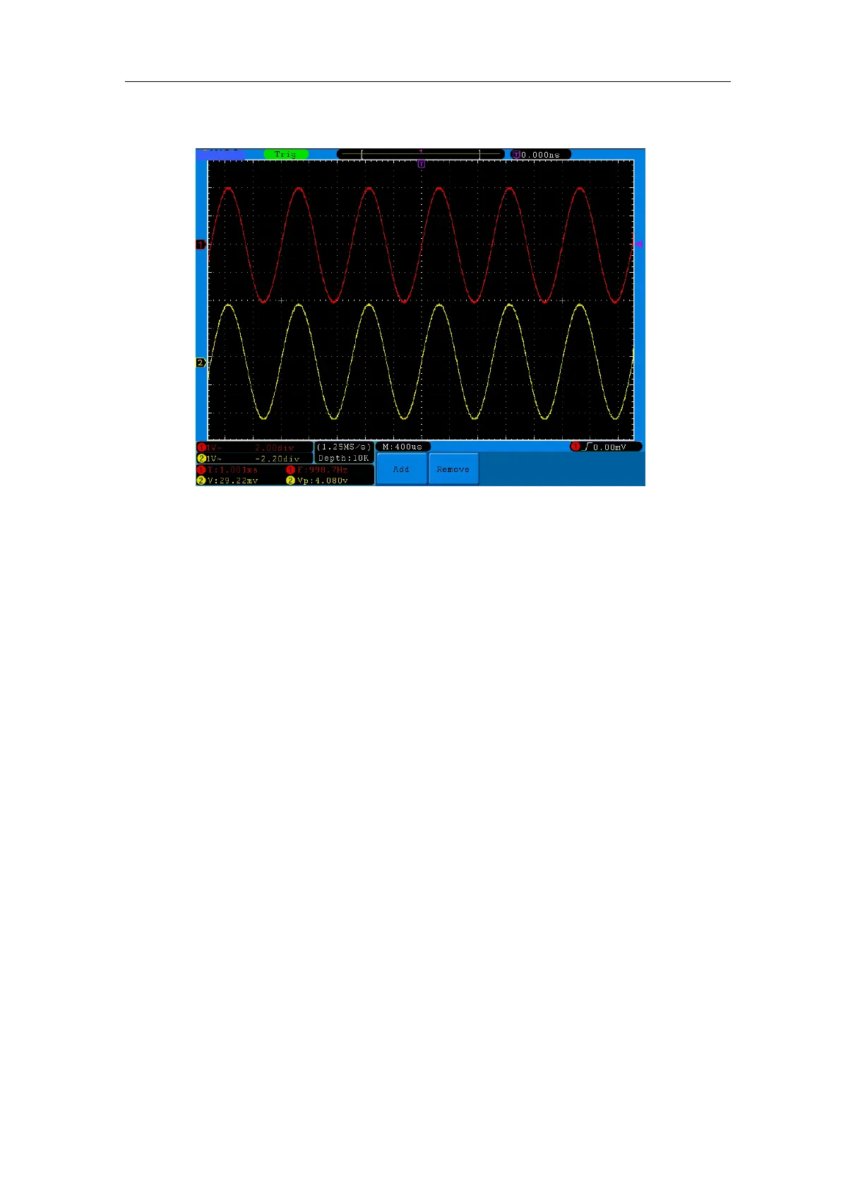
Then, the period, frequency, mean and peak-to-peak voltage will be displayed at the
bottom left of the screen and change periodically (see Figure 7-1).
Figure 7-1 Measure Frequency and PK-PK value for a given signal
Example 2: Gain of a Amplifier in a Metering Circuit
The purpose of this example is to work out the Gain of an Amplifier in a Metering
Circuit. First we use Oscilloscope to measure the amplitude of input signal and output
signal from the circuit, then to work out the Gain by using given formulas.
Set the probe menu attenuation coefficient as 10X and that of the switch in the probe
as 10X (see "How to Set the Probe Attenuation Coefficient" on P14).
Connect the oscilloscope CH1 channel with the circuit signal input end and the CH2
channel to the output end.
Operation Steps:
(1) Press the Autoset button and the oscilloscope will automatically adjust the
waveforms of the two channels into the proper display state.
(2) Press the Measure button to show the Measure menu.
(3) Press the H1 button.
(4) Press the F2 button and choose CH1.
(5) Press the F1 button and turn the M rotary control to choose PK-PK.
(6) Press the F2 button and choose CH2.
(7) Press the F1 button again and turn the M rotary control to choose PK-PK.
(8) Read the peak-to-peak voltages of Channel 1 and Channel 2 from the bottom left
of the screen (See Figure 7-2).