User Manual
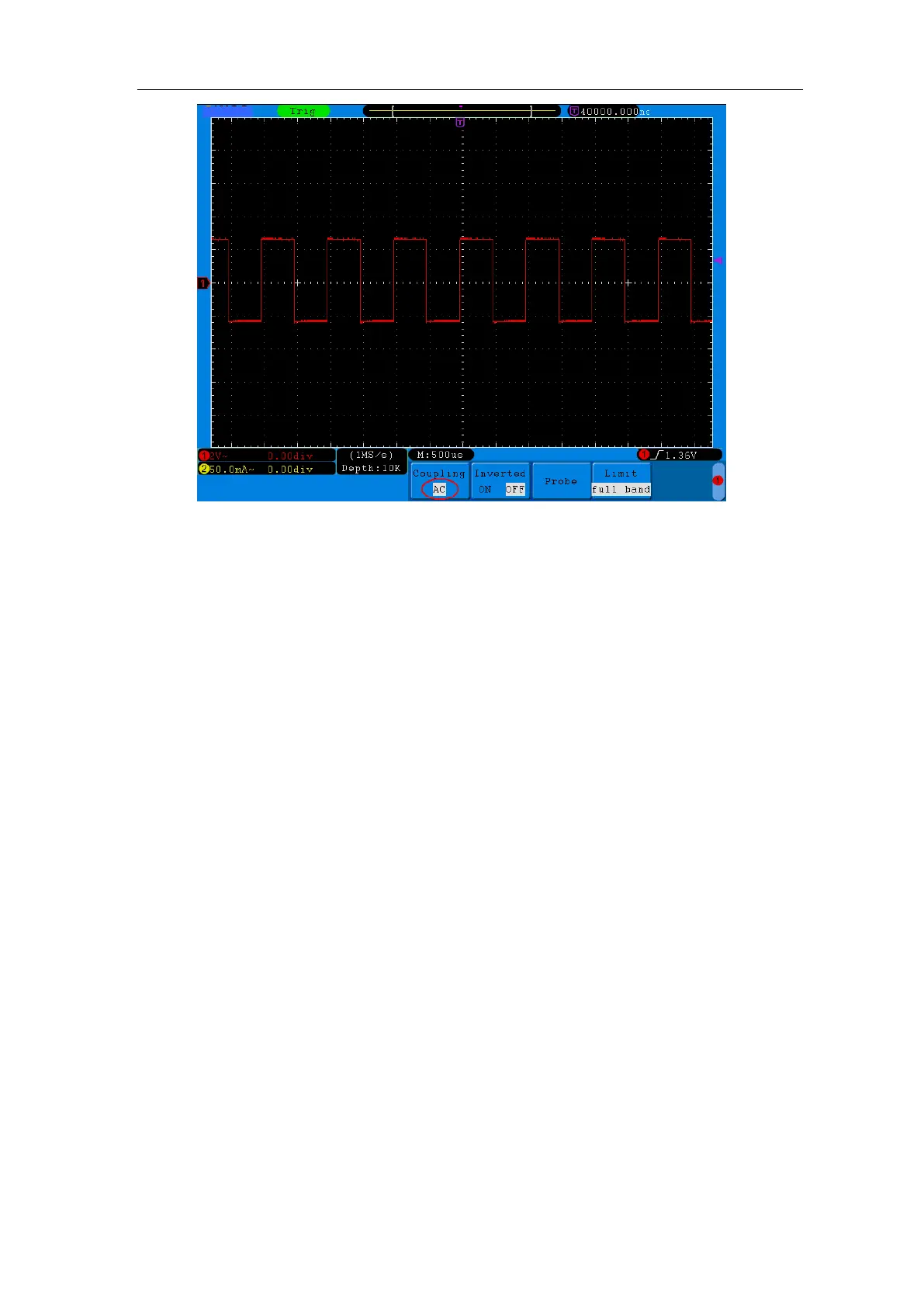
Figure 5-2 AC Coupling Oscillogram
2. To adjust the probe attenuation
For correct measurements, the attenuation coefficient settings in the operating
menu of the Channel should always match what is on the probe (see "How to Set
the Probe Attenuation Coefficient" on P14). If the attenuation coefficient of the
probe is 1:1, the menu setting of the input channel should be set to X1.
Take the Channel 1 as an example, the attenuation coefficient of the probe is 10:1,
the operation steps are shown as follows:
(1) Press the CH1 MENU button to show the CH1 SETUP menu.
(2) Press the H3 menu selection, the Probe menu will display at the right of the
screen. Press the F1 button to select Attenu. In the menu at the left of the
screen, turn the M rotary control to select X10 for the probe.
The Figure 5-3 illustrates the setting and the vertical scale factor when the probe
of the attenuation coefficient of 10:1 is used.