Manual# I27028 7-6 Rev. 2 – 11/22/2017
find the wiring diagram for the heating elements. If an element is operational, there
should be a resistance of a few Ohms through the element. An open circuit or a
high resistance indicates a failed element.
7.4 CHECKING THE GAS MODULATION VALVE
The gas modulation valve is controlled by the PLC, based on the temperature at the
reactivation outlet. The amount of energy required depends on the moisture load and
the temperature of the air entering the burner. The gas modulation valve changes the
amount of gas input to react to changes in energy demand. When the burner needs
less energy, the valve will reduce the gas flow. The modulation valve may be allowed to
close completely. Some gas will still flow to the burner.
The simplest way to check this system is to monitor the control output from the PLC, and
the position of the modulation valve. To check the output from the PLC, use a DC
voltmeter. (The signal should be from 0-10VDC)
1. When the unit is first turned on, the control system should be calling for maximum
heat and the voltage supplied to the modulation valve should be rising to10 Volts.
2. As the demand for heat is reduced, the control system will gradually close the
modulation valve.
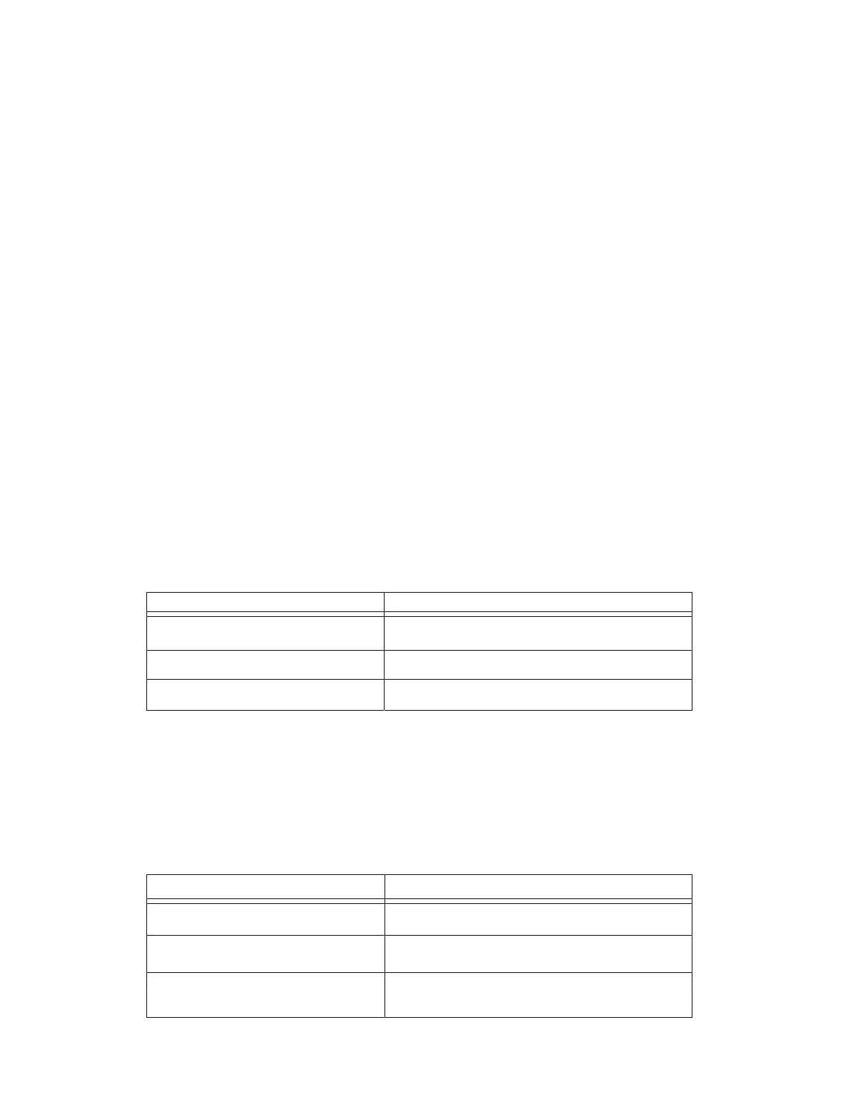
7.5 CHECKING THE AIRFLOW SWITCH
The airflow switch (AFS1) senses the reactivation air flow. If the reactivation airflow
drops below a preset limit, this control will de-energize the burner control circuit. Use a
Volt/Ohmmeter to check the 110VAC signal from the switch. See the wiring diagram
included in this manual. The table below shows how the switch should behave.
Machine
function
Switch
behavior
Unit switched off
Contacts normally open, infinite resistance across
switch
Unit running Contacts closed, no voltage drop across switch
Abnormally low reactivation air flow Contacts open, 110VAC across switch
7.6 CHECKING THE HIGH TEMPERATURE LIMIT SWITCH
The high temperature limit switch (TS01) senses the temperature of the reactivation air
entering the dehumidifier. The thermocouple is placed downstream of the reactivation
heater, and upstream of the HoneyCombe® wheel. The setpoint is factory set at 350°F
and does not require adjustment. (Higher temperatures may damage the wheel.) If the
temperature rises above the setpoint, the dehumidifier will shut down and lock into a
fault condition. The following table shows how the switch should behave:
Machine
function
Switch
behavior
Unit switched off
Contacts, normally closed, no resistance across
switch
Unit running Contacts close, no voltage drop across switch
Temperature above temperature switch
fault setpoint
Contacts open, 110V AC across switch
 Loading...