Manual# I27028 7-5 Rev. 2 – 11/22/2017
7.2 CHECKING THE POWER DISTRIBUTION SYSTEM
For details of the power distribution system, see the Wiring Diagram.
1. If supplied, the three-phase AC entering the unit is checked by a three-phase power
monitor (PMO1). If one of the phases is missing, or if the rotation of the motors is
reversed, a red LED on this unit will light. The power monitor is also tied to the E-
Stop interlock circuit.
2. The contactor for each of the motors (OLRx) has integral short-circuit and overload
protection. An overload will trigger a fault indication on the front panel (3 flashes).
A short-circuit will trip the contactor. It can be reset by pressing a button on the
front of the unit.
3. A thermocouple (TC01) senses the reactivation outlet temperature.
Based on the input from TC01 and TC02, the PLC uses solid-state relays (SSR1) to
control or modulate the output of the first set of heating elements. Each SSR
receives an analog input from the PLC, and switches one phase of the AC to the
heating elements. When the SSR is receiving the analog input, and is supposed to
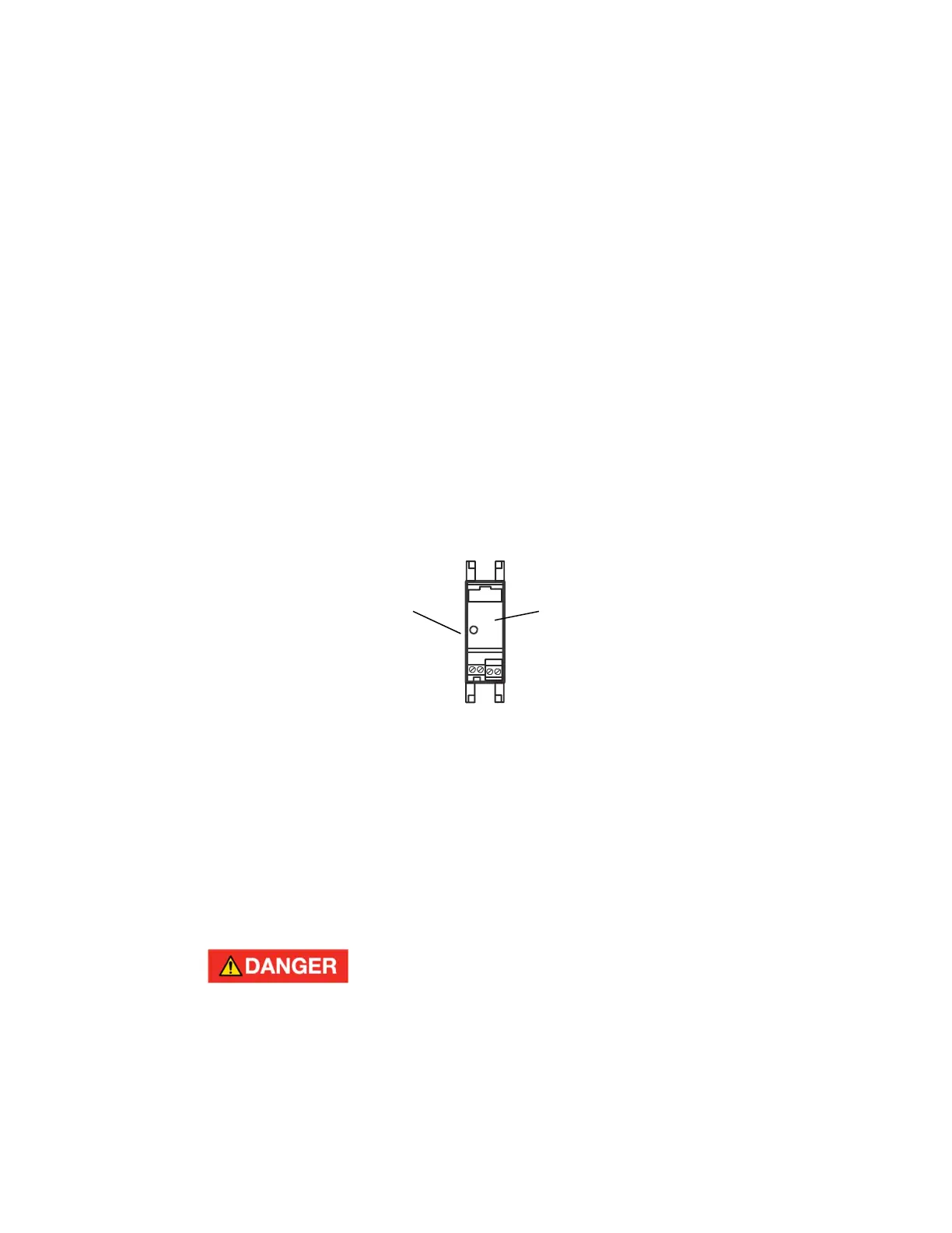
be turned on, an amber LED on the SSR lights. See Figure 7-1. Whenever the
amber LED is on, the SSR should be producing an output.
Figure 7-1
SOLID STATE RELAY
Each additional heating zone can be switched on by the PLC via a contactor. As
additional heating is required, the PLC turns on these additional zones. The total
heat output is still "fine-tuned" by the PLC modulating the first zone via the SSR.
7.3 CHECKING THE HEATING ELEMENTS
1. The heating elements are located in the intake side of the reactivation air stream
(upstream of the desiccant wheel).
2. Turn off the power to the unit!
Turn off the power to the R-Series unit before working with the
heating elements. These parts carry high voltage and current
which can result in death or cause severe burning. Set the
Auto/Off/Manual switch to the Off position. Follow standard lock-
out tag-out procedures.
3. Remove the cover on the heater element housing.
4. To check the elements, remove the buss bars which connect the individual heating
elements. Check the resistance across each of the heating elements using an
Ohmmeter. Check inside the heater compartment, on the underside of the cover, to
LED
(amber)
Solid state relay
(SSR)
 Loading...