© Munters AB, 2020 13
3.3
Layout
•
Board Layout
•
External Device Specifications
3.3.1
B
OARD
L
AYOUT
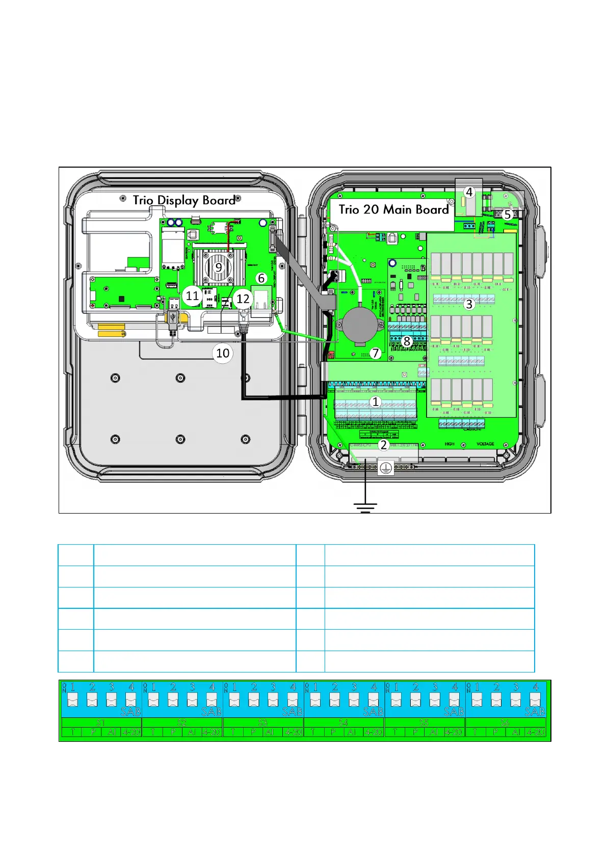
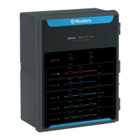
Figure 2: Board layout
1 Analog/digital ports 7 Dipswitches
2 Ground strip 8 Trio Scale Card
3 20 relays 9 Heat Sink
4 Alarm relay 10 Wireless antenna
5 Power ports 11 SIM card port
6 Ethernet port 12 SD card port
Figure 3: Dipswitches, expanded
•
One dipswitch only in each set is raised.
•
Only raise a dipswitch if a device is wired to an S port.