(Revised 2011-07-21) Page 93 of 158
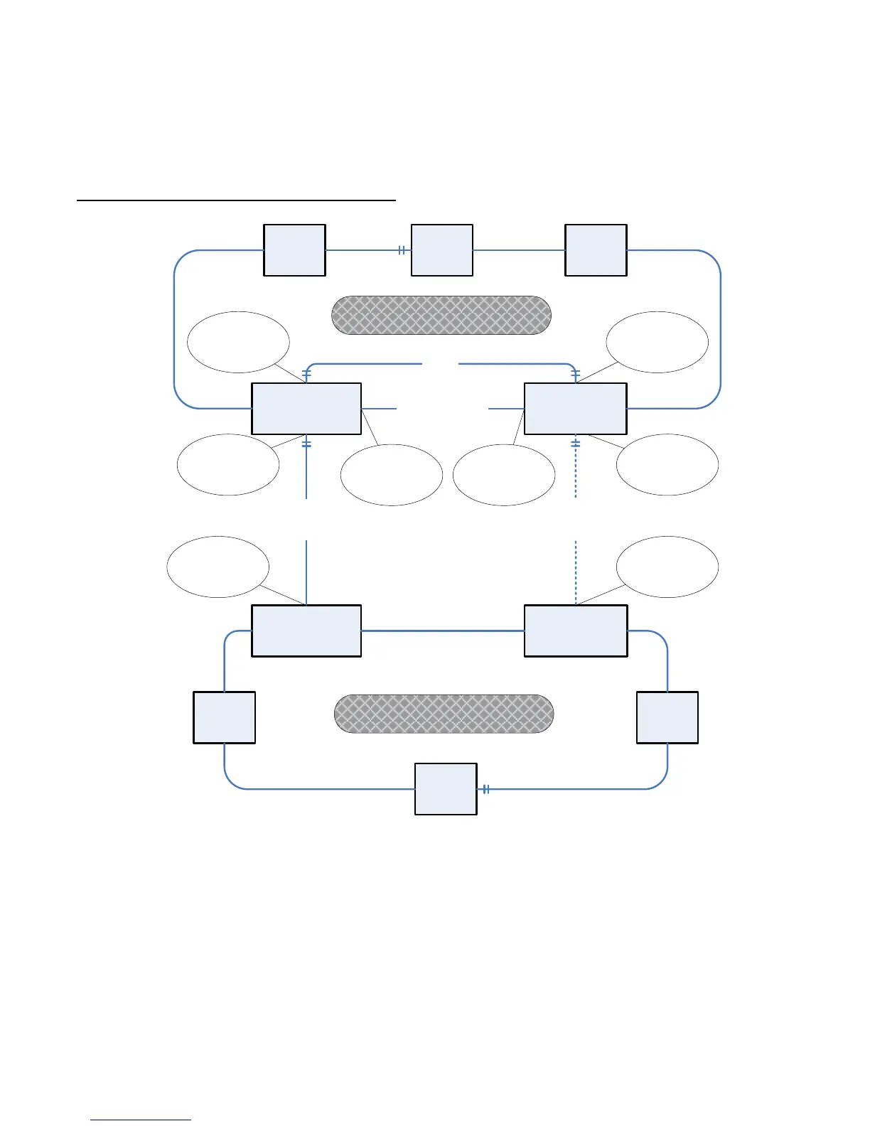
N-Link – Configuration
The purpose of N-Link is to provide a way to redundantly couple an N-Ring topology to one or more other
topologies, usually other N-Ring topologies. Each N-Link configuration requires 4 switches: N-Link
Master, N-Link Slave, N-Link Primary Coupler, and N-Link Standby Coupler.
Standard N-Link Configuration (Example):
N-Rng
Manager
N-Ring
Auto
Member
N-Link Slave
N-Ring Member
N-Link Master
N-Ring Member
Partner Link
(N-Ring Segment)
Control
Link
N-Ring
Auto
Member
N-Rng
Manager
N-Link Coupler
N-Ring Member
N-Link Couper
N-Ring Member
N-Ring
Auto
Member
N-Ring
Auto
Member
Primary
Coupler
Link
Standby
Coupler
Link
Coupler Port
(Default: TX4)
Control Port
(Auto-Detected)
Coupler Port
(Default: TX4)
Control Port
Default: TX3
Partner Port
(Auto-Detcted)
Partner Port
(Auto-Detcted)
N-Ring #1
N-Ring #2
Coupler Port
(Auto-Detected)
Coupler Port
(Auto-Detected)
For convenience, a diagram similar to the above is provided in the switch‘s browser help for N-Link.
 Loading...