EN
W415-2036 / D / 08.05.21
25
maintenance
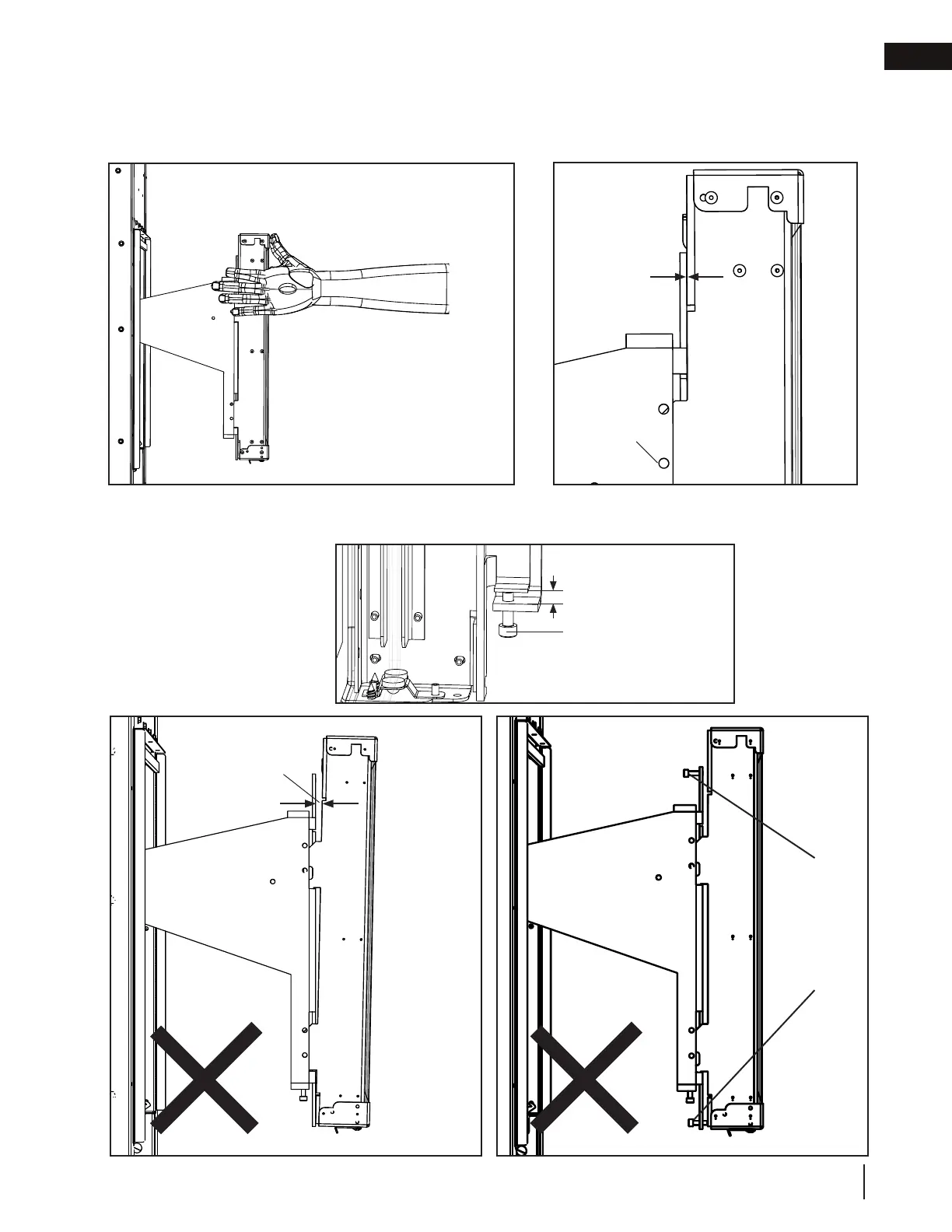
Clear line
of sight
Typically 1/8”
Vertical Adjustment
Screw
DO’S
DON’TS
Hold GGA-1 and GGA-1 slider bracket together firmly whilst
tightening fasteners. Repeat on other end of GGA-1.
Ensure there is no gap between back of GGA-1
and GGA-1 slider bracket at top and/or bottom.
Repeat on other end of GGA-1.
Gap
Horizontal
adjustment
screws
installed
unevenly
and/or
prematurely.
No gap
Fig. 11Fig. 10
Fig. 10
Fig. 8
Fig. 7
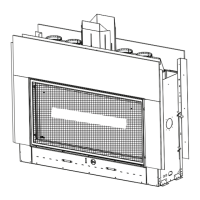
8. The GGA-1 mount bracket holes should be lined up with the screw holes of the GGA-1 slider brackets
to ensure a clear line of sight (Fig. 8). It is typically necessary to raise the GGA-1 on both sides using
the vertical adjustment screws. Raising the GGA-1 approximately 1/8” typically provides the optimum
preliminary fit (Fig. 9). Repeat on other end of GGA-1.