VS1 Operations and Maintenance Manual Operating the transmitter
Page 2-148 Issue 3.1 2013-10-01
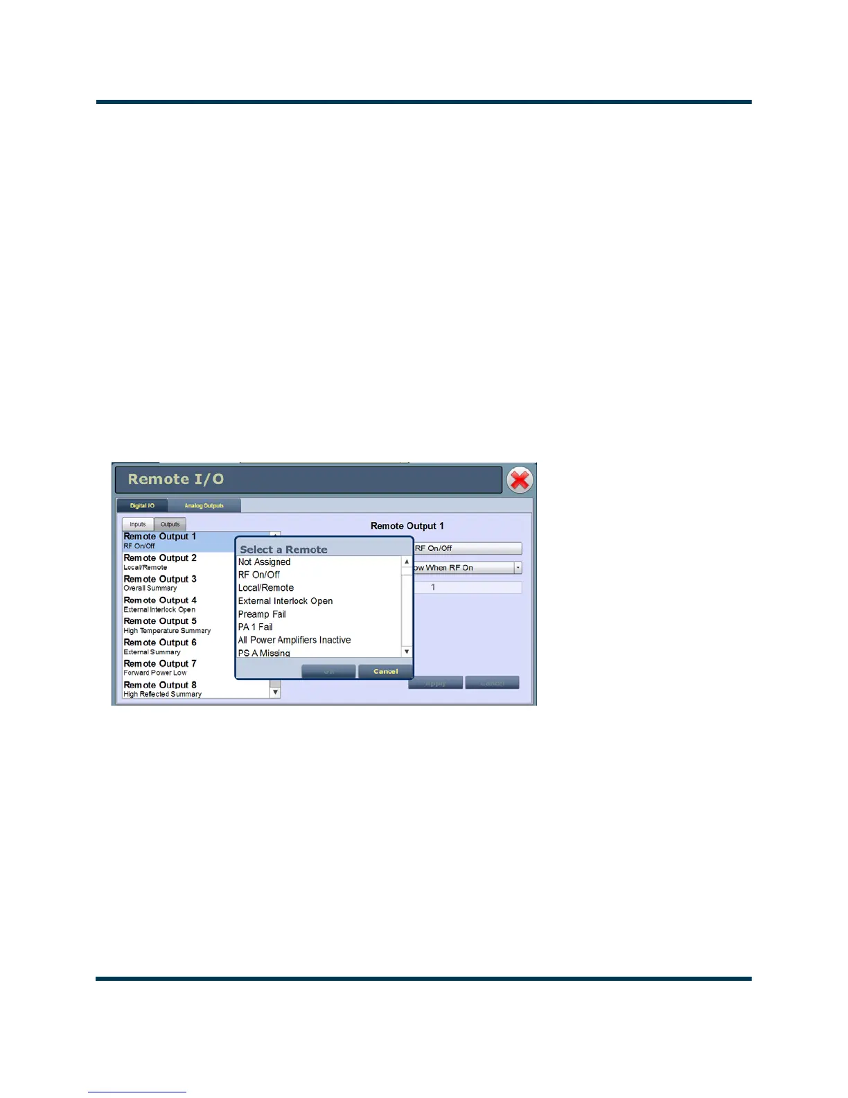
Select output channel - AUI
You can configure digital outputs 1 through 16 to monitor a variety of alarm and status outputs. Click
the existing Channel bar to display the Select a Remote window. From this window, select one of the
channels, then click Load to accept:
• Not Assigned. No alarm or status parameter is monitored.
• Local/Remote. The active logic level indicates local only control. The inactive logic level
indicates remote enabled.
• RF On/Off. The active logic level indicates the transmitter’s RF power stage is on (enabled).
The inactive logic level indicates the transmitter’s RF power stage is off.
• Preset Status (1-4 default). The active preset’s output will be indicated by a logic low. The
remaining, non-active preset outputs will be open collector.
• Various Alarms. The active logic level indicates that the selected alarm is occurring. Any
transmitter alarm can be selected as a digital output. Refer to the VS1 Troubleshooting Manual
for a description of each alarm.
Figure 2.132:
Configure output control logic - AUI
You can configure the active/inactive logic for each of the 16 digital outputs. Click the existing Logic
bar to display the applicable drop-down menu options. Some digital output default examples:
if the selected channel is
RF On/Off, the drop-down options are:
•
Output Low When RF On. Logic ‘0’ (low) indicates the output is true (RF is on); Logic ‘1’
(high) indicates the output is false (RF is off).