VS1 Operations and Maintenance Manual Operating the transmitter
Issue 3.1 2013-10-01 Page 2-147
• Active High, Increase. Logic ‘1’ (high) causes a power increase.
• Active Low, Increase. Logic ‘0’ (low) causes a power increase.
• Active High, Decrease. Logic ‘1’ (high) causes a power decrease.
• Active Low, Decrease. Logic ‘0’ (low) causes a power decrease.
Click Apply to activate changes. Click Undo to cancel changes.
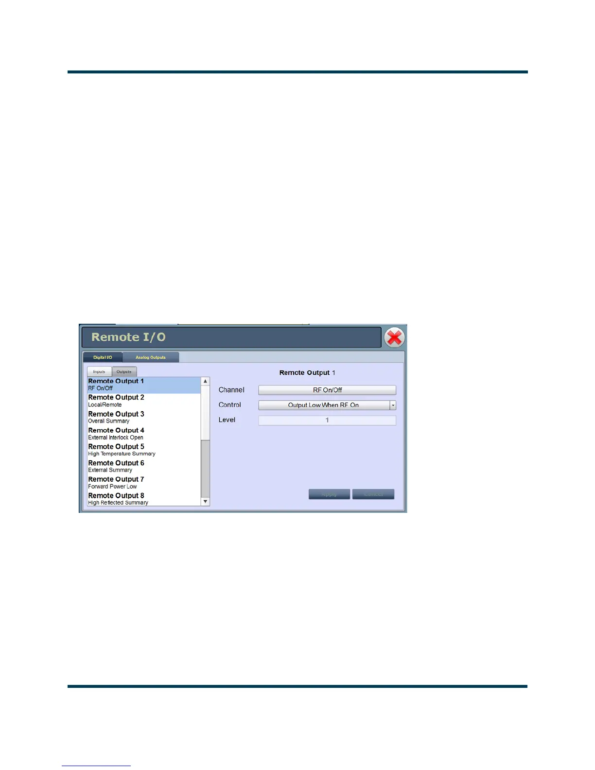
Digital outputs - AUI
Using the Digital Outputs Page - see Figure 2.131, you can configure up to 16 digital outputs that
indicate either the presence of various alarms or the status of operator controlled circuits.
Nautel presets the digital outputs prior to shipping. See the VS1 Pre-installation Manual for details.
Figure 2.131: Digital Outputs Page
Select the desired digital output (1 through 16) from the list. The Channel and Logic settings for the
selected output, as well as the current logic level (1 or 0), are displayed on the right-hand side of the
page. You can define the Channel and Logic settings as follows: