E2600 Controller-Drive Tray Installation Guide 98
Table 17 Drive State Represented by LEDs
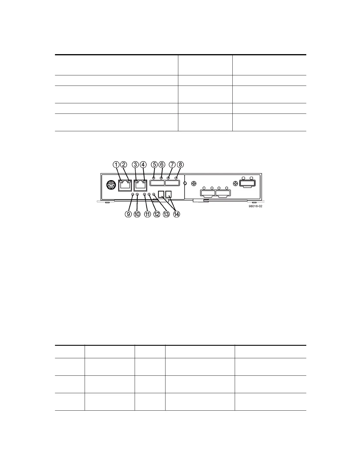
LEDs on the Controller Canister Main Faceplate
Figure 91 LEDs on the Controller Canister Main Faceplate
1. Ethernet Connector 1 Link Rate LED
2. Ethernet Connector 1 Link Active LED
3. Ethernet Connector 2 Link Rate LED
4. Ethernet Connector 1 Link Active LED
5. Host Link 1 Service Action Required LED
6. Host Link 1 Service Action Allowed LED
7. Host Link 2 Service Action Required LED
8. Host Link 2 Service Action Allowed LED
9. Battery Service Action Required LED
10. Battery Charging LED
11. Controller Service Action Allowed LED
12. Controller Service Action Required LED
13. Cache Active LED
14. Seven-Segment Tray ID
Table 18 LEDs on the Controller Canister Main Faceplate
Drive State
Drive Power LED
(Green)
Drive Service Action
Required LED (Amber)
Power is not applied. Off Off
Normal operation – The power is turned on, but
drive I/O activity is not occurring.
On Off
Normal operation – Drive I/O activity is occurring. Blinking Off
Service action required – A fault condition exists,
and the drive is offline.
On On
Location LED Color On Off
1 Ethernet Connector
1 Link Rate LED
Green There is a 100BASE-T rate. There is a 10BASE-T rate.
2 Ethernet Connector
1 Link Active LED
Green The link is up (LED blinks
when there is activity).
The link is not active.
3 Ethernet Connector
2 Link Rate LED
Green There is a 100BASE-T rate. There is a 10BASE-T rate.