E2600 Controller-Drive Tray Installation Guide 101
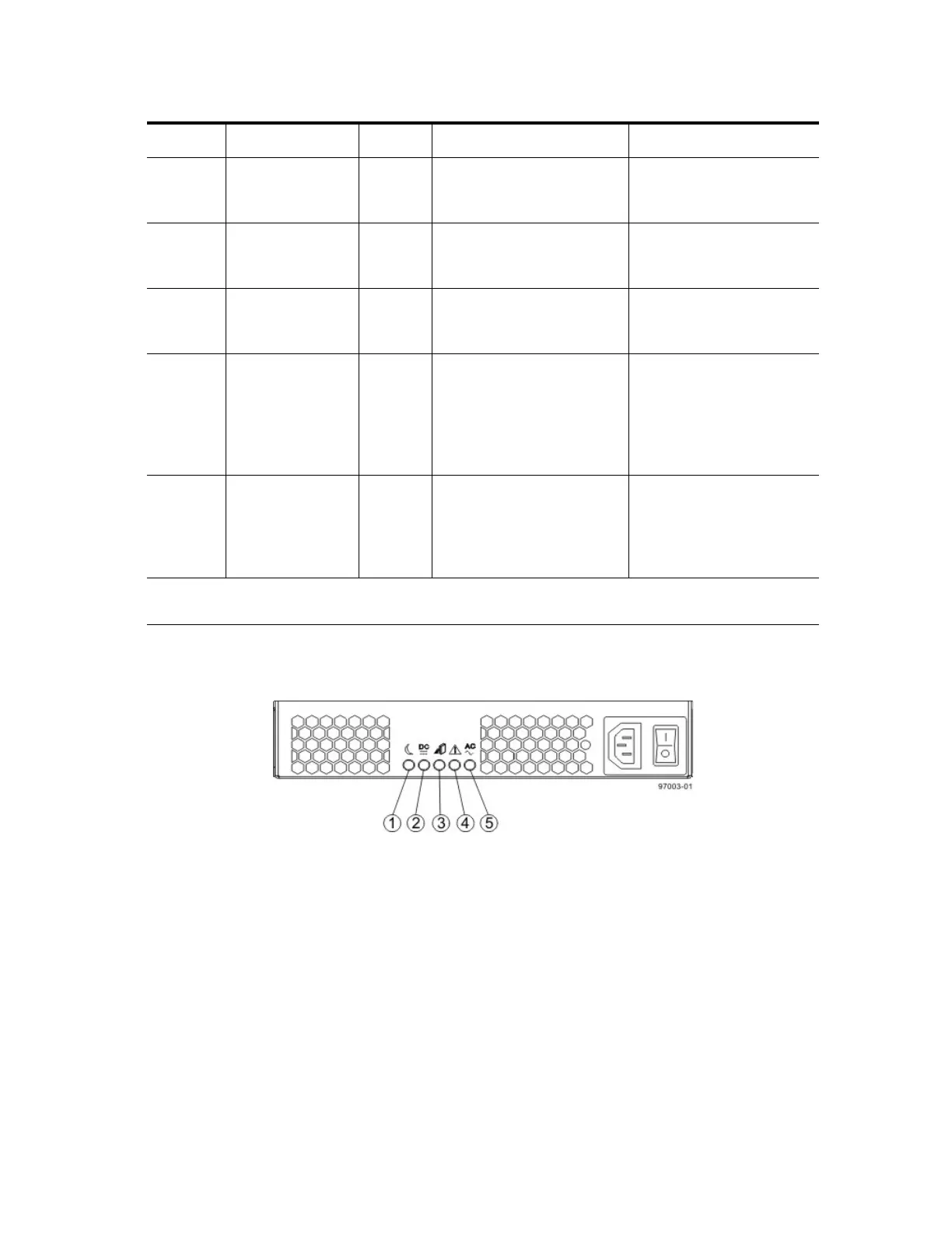
LEDs on the Power-Fan Canister
Figure 93 LEDs on the Power-Fan Canister
1. Standby Power LED
2. Power-Fan DC Power LED
3. Power-Fan Service Action Allowed LED
4. Power-Fan Service Action Required LED
5. Power-Fan AC Power LED
6 Host Interface
Card Link 5 Active
LED
Green The link is up (LED blinks
when there is activity).
The link is not active.
7 Host Interface
Card Link 6 Up
LED
Green The Ethernet link has
auto-negotiated to 1 Gb/s.
The Ethernet link is down or
does not auto-negotiate to 1
Gb/s.
8 Host Interface
Card Link 6 Active
LED
Green The link is up (LED blinks
when there is activity).
The link is not active.
9 Expansion Fault
LED
Amber At least one of the four PHY
is working, but another PHY
cannot establish the same
link to the device connected
to the Expansion OUT
connector.
Normal status.
10 Expansion Active
LED
Green At least one of the four PHYs
in the OUT connector is
working and a link has been
made to the device connected
to the Expansion connector.
The link is not active.
* "LEDs on the Controller Canister Host Interface Card Subplates" on page 100 shows the four-port
iSCSI host interface card (HIC), which also can be a four-port FC HIC or a two-port SAS HIC.
Location LED Color On Off