E2600 Controller-Drive Tray Installation Guide 103
Table 21 LEDs on the Left End Cap
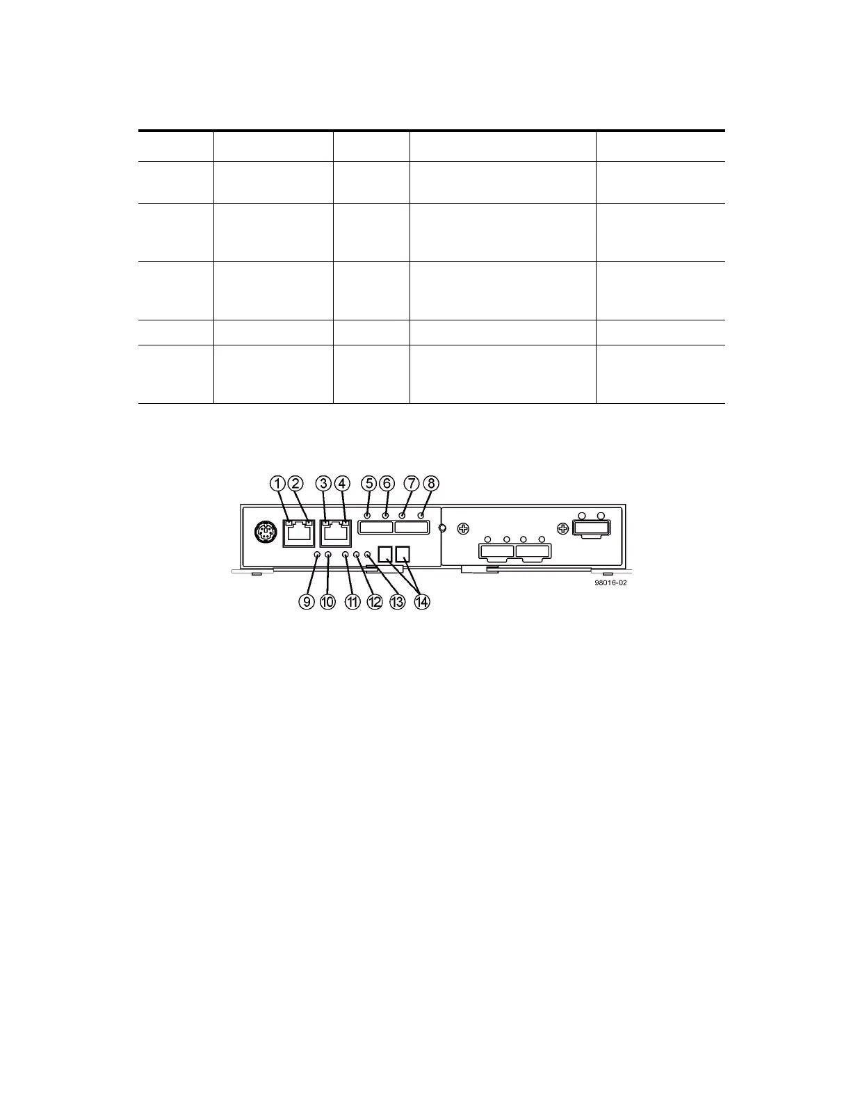
LEDs on the Controller Canister Main Faceplate
Figure 95 LEDs on the Controller Canister Main Faceplate
1. Ethernet Connector 1 Link Rate LED
2. Ethernet Connector 1 Link Active LED
3. Ethernet Connector 2 Link Rate LED
4. Ethernet Connector 1 Link Active LED
5. Host Link 1 Service Action Required LED
6. Host Link 1 Service Action Allowed LED
7. Host Link 2 Service Action Required LED
8. Host Link 2 Service Action Allowed LED
9. Battery Service Action Required LED
10. Battery Charging LED
11. Controller Service Action Allowed LED
12. Controller Service Action Required LED
13. Cache Active LED
14. Seven-Segment Tray ID
Location LED Color On Off
1 Controller-Drive
Tray Locate
White Identifies a controller-drive
tray that you are trying to find.
Normal status.
2 Service Action
Required
Amber A component within the
controller-drive tray needs
attention.
Normal status.
3 Controller-Drive
Tray
Over-Temperature
Amber The temperature of the
controller-drive tray has
reached an unsafe level.
Normal status.
4 Power Green Power is present. Power is not present.
5 Standby Power Green The controller-drive tray is in
Standby Power mode.
The controller-drive
tray is not in Standby
Power mode.