E2600 Controller-Drive Tray Installation Guide 115
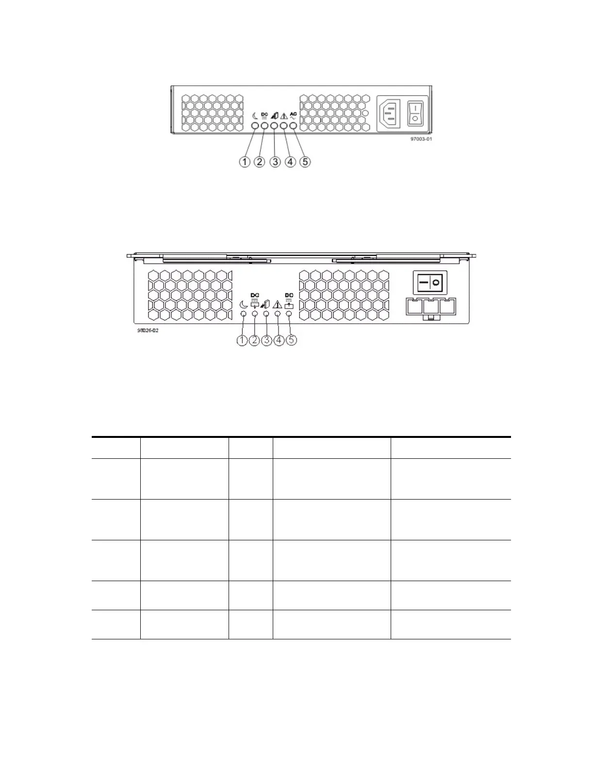
Figure 101 LEDs on the AC Power-Fan Canister
1. Standby Power LED
2. Power-Fan Output DC Power LED
3. Power-Fan Service Action Allowed LED
4. Power-Fan Service Action Required LED
5. Power-Fan Input AC Power LED
Figure 102 LEDs on the DC Power-Fan Canister
1. Standby Power LED
2. Power-Fan Output DC Power LED
3. Power-Fan Service Action Allowed LED
4. Power-Fan Service Action Required LED
5. Power-Fan Input DC Power LED
Table 30 LEDs on the Power-Fan Canister
Location LED Color On Off
1 Standby Power Green The drive tray is in Standby
mode, and DC power is not
available.
The drive tray is not in
Standby mode, and DC
power is available.
2 Power-Fan DC
Power
Green DC power from the
power-fan canister is
available.
DC power from the
power-fan canister is not
available.
3 Power-Fan Service
Action Allowed
Blue The power-fan canister can
be removed safely from the
drive tray.
The power-fan canister
cannot be removed safely
from the drive tray.
4 Power-Fan Service
Action Required
Amber A fault exists within the
power-fan canister.
Normal status.
5 Power-Fan AC
Power
Green AC power to the power-fan
canister is present.
AC power to the power-fan
canister is not present.